
Thick Plates Under Bending
Sample Applications
Thick Plates Under Bending
Effect of bending on crack development in thick plates
This example demonstrates the effect of bending on the development of long cracks in thick plate structures. The work was undertaken as part of a project investigating the safety of ship structures. Additional information on the analysis can be found in the reference given below.
The geometry for the analysis is a 15mm thick plate with a centre crack. The half symmetry model of the uncracked mesh is shown in Figure 1 with the required crack position indicated. The plate width is 250mm (in the half model). The initial crack is defined by 2a/W=0.23, giving a length of 57.5mm (in the half model), with the crack front straight and normal to the plate surfaces. In order to accommodate this crack size, element boundaries in the mesh are shifted by Zencrack when the crack is inserted. This reduces element distortion and is shown in the animation of figure 2.
Analyses were conducted for four load cases (with a stress ratio of zero): pure tension (zero bending); 10% bending; 20% bending; and 40% bending (e.g. 40% bending is defined by membrane stress of 100MPa plus an out-of-plane bending moment which gives a peak stress of ±40MPa). Fatigue crack growth predictions were made using a Paris law and standard C and n constants for structural steel. No fracture toughness values were defined to stop the analysis and the crack was allowed to grow to the edge of the plate.
Figures 3 and 4 show the effect of bending on the shape development of the crack. (Animations are available for the four pictures in Figure 3 via the links under the pictures). For the pure tension case the crack front develops a small amount of curvature but the shape, as might be expected, is symmetric through the plate thickness. The bending cases show an increasing curvature in the crack front shape with increasing bending.
Figure 5 shows the effect of 40% bending on the life, which is reduced by less than 10% compared to a pure tension stress of 100MPa. If, as a conservative assumption, the stress on the tensile surface had been used for the fatigue crack growth prediction (i.e. assuming a pure tensile stress of 140MPa), the predicted life would have been reduced by a factor of three compared to a tension stress of 100MPa. The analysis is therefore able to quantify the conservatism in that assumption.
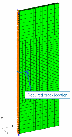
Figure 5 - Crack growth profile comparisons for different amounts of bending
Figure 6 - Effect of 40% bending on life compared with no bending
References
Stress Intensity Factors For Cracked Plates Under Out-of-plane Bending
M.R. Roy, J.D.G. Sumpter, QinetiQ, Rosyth Business Park, Dunfermline
C. Timbrell, M. Wiehahn, Zentech International Ltd.
Abaqus Users' Conference, Stockholm, Sweden, May 18-20 2005.
Acknowledgements
This model is shown with the agreement of Michael Roy and John Sumpter, QinetiQ, Dunfermline, Scotland.