Circular Shaft
Sample Applications
Circular Shaft
Mixed mode crack growth in a circular shaft
This example demonstrates the effect of mode I and mixed mode loading on a crack in a circular shaft. This analysis is typical of many industrial applications. The initial crack is a shallow but straight through crack at the centre of a test specimen. The full uncracked mesh is shown in Figure 1. The cut-away cross section at the crack location is shown in Figure 2 for the uncracked mesh and in Figure 3 for the mesh containing the initial straight crack.
Figure 1 - The component to be analysed
Figure 2 - Uncracked model cut along the mid section showing the plane that will contain the initial crack front
Figure 3 - The initial cracked model for the planar growth analysis showing (one side of) the straight crack front in the crack plane
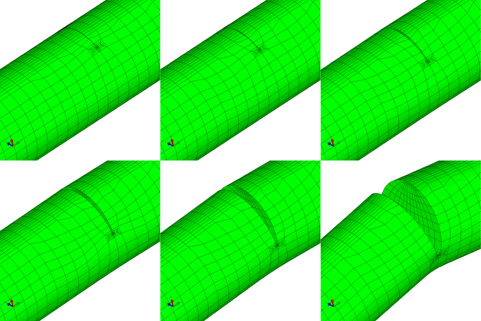
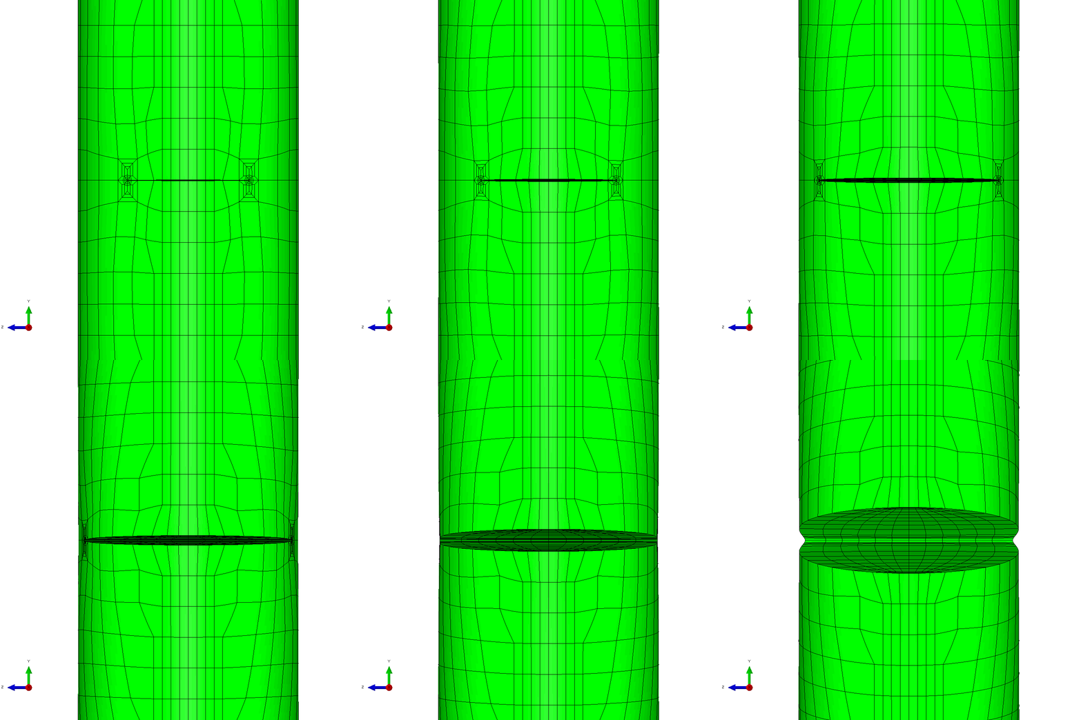
In the first example, the component is loaded by constant amplitude cyclic tension. This generates planar crack growth in which the crack front develops a curved shape within the initial crack plane. Figure 4 shows the calculated profiles from the growth analysis. Plots of the meshing through the analysis are shown in Figure 5.
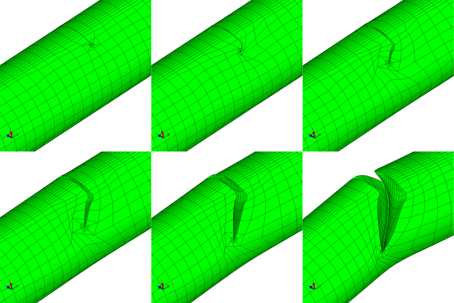
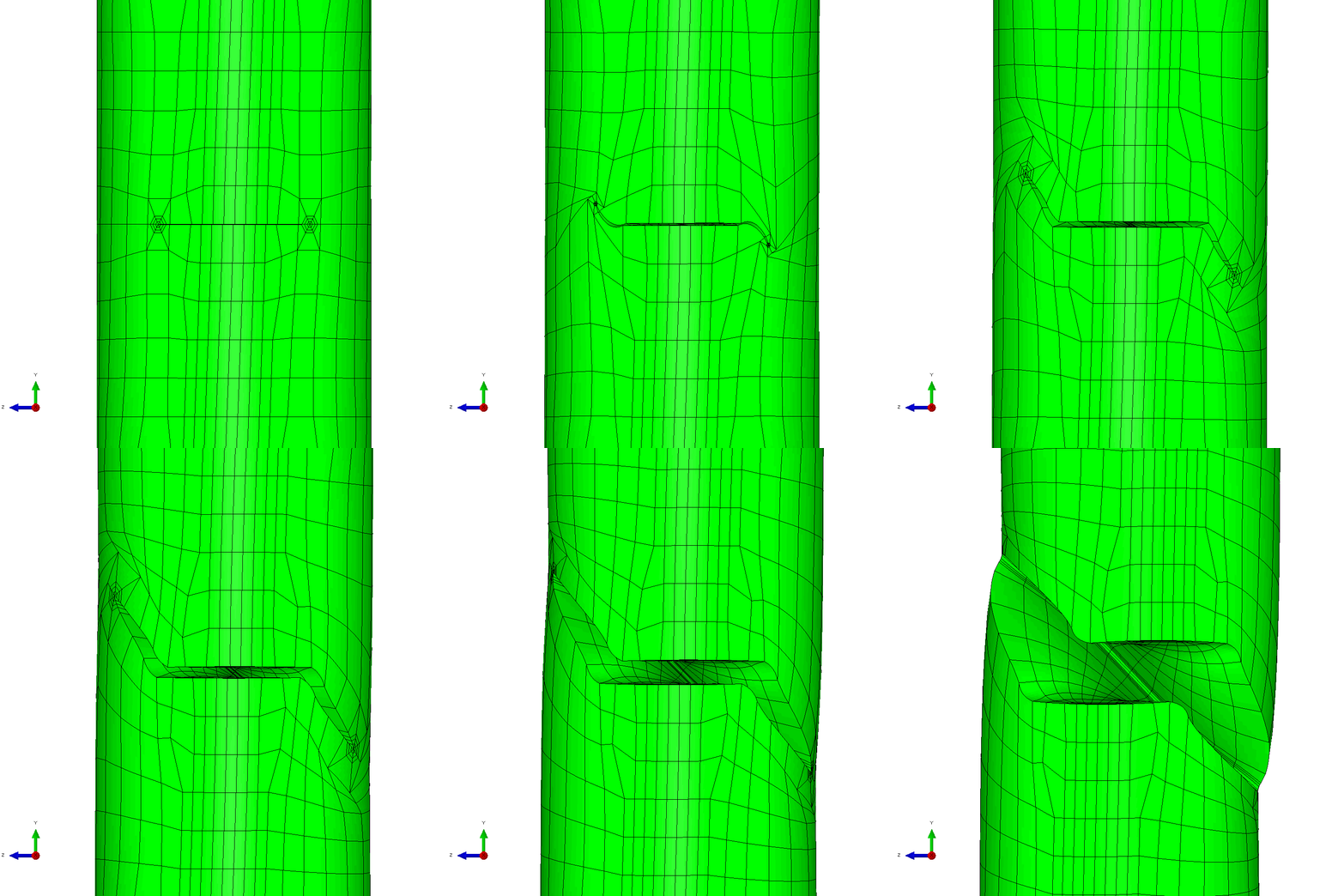
The mixed mode case is a more challenging one. The input requires only a small number of changes to develop an analysis with in-phase constant amplitude tension and torsion. This generates an initial anti-symmetric mixed mode condition at the crack front. The result is that the crack skews and twists as it grows through the section to try to achieve a mode I configuration at the crack front. Figure 6 shows the calculated profiles from the growth analysis. Plots of the meshing through the analysis are shown in Figure 7 and demonstrate the way that Zencrack is able to propagate a non-planar 3D crack shape through a structure.
The mixed-mode load case for this specimen is also available as an example using the remeshing method.


Figure 5 - Analysis with cyclic tension load resulting in planar crack growth


Figure 7 - Analysis with cyclic tension and torsion load resulting in non-planar crack growth