- Software
- Zencrack Support
- F.E. Interfaces Support
Finite element interface to Simcenter Nastran
F.E. Interfaces Support
Finite element interface to Simcenter Nastran
This page gives information on the interface to Simcenter Nastran (formerly NX Nastran) that may help in running jobs and improving the performance you obtain with this interface. Some key items that you may have missed in the user manual are also included.
Which versions of Simcenter Nastran and NX Nastran is Zencrack interfaced to?
Zencrack is interfaced to Simcenter Nastran. Testing has been conducted up to and including Simcenter Nastran 2512.
Note that:
- The interface supports solution types SOL101 and SOL401. The use of the J-integral option requires SOL401.
- In the old terminology, Zencrack also operates with NX Nastran. At least Version 10.0 of NX Nastran is required - earlier releases are not supported.
What Simcenter Nastran license type is required?
Simcenter Nastran Desktop licenses include a checksum in input files created by their associated pre-processor which only allows execution of the file as generated by the pre-processor. This prevents uses of this type of input file with Zencrack since a fundamental part of the process is that Zencrack modifies the input file.
Enterprise licensing enables Simcenter Nastran to solve any valid Nastran input file from any pre-processor, including after modifications by Zencrack.
Simcenter Nastran can exist as a basic package with additional modules. Zencrack requires SOL101 as a minimum and Simcenter Nastran Multistep Nonlinear SOL401 for calculation of J-integrals.
If the "modified input file" requirement is satisfied and appropriate SOL types are available, Zencrack can use Simcenter Nastran as part of a stand-alone installation or when Simcenter Nastran is packaged within Simcenter3D or Femap.
Which SOL types does Zencrack support?
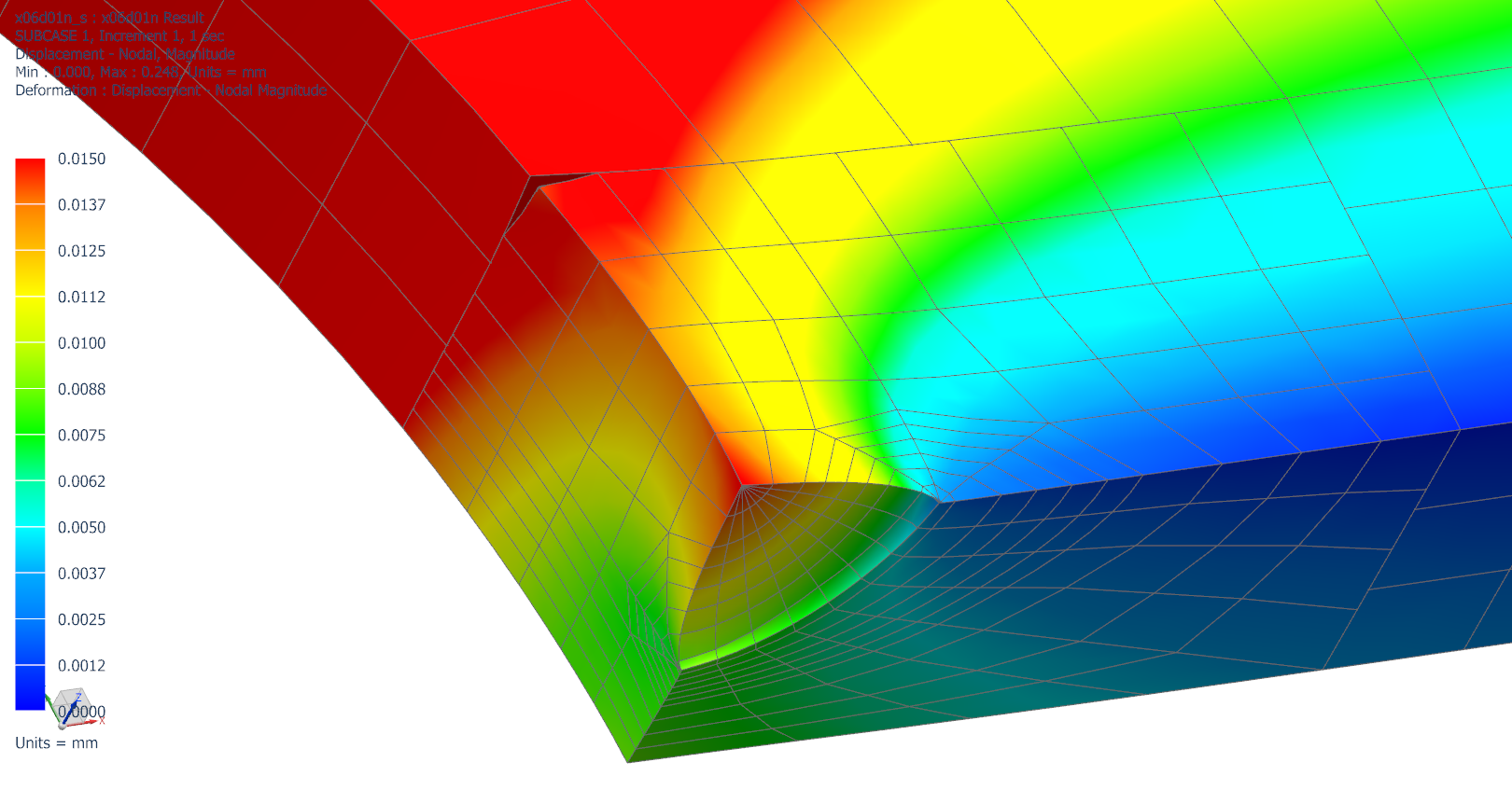
Solution types 101 and 401 are supported for a Zencrack analysis. Fracture mechanics parameters at nodes along the crack front are available as follows:
- SOL101
- The stress intensity factors KI, KII and KIII calculated from nodal displacements (linear elastic isotropic materials).
- SOL401
- J-integrals via the Simcenter Nastran CRAKTP and VCEV options.
- The stress intensity factors KI, KII and KIII calculated from nodal displacements (linear elastic isotropic materials).
If an analysis uses SOL101 then fracture mechanics parameters are calculated using the displacements from the f.e. solution. If SOL401 is used, the analysis calculates two sets of fracture mechanics parameters: one using displacements and one using J-integral results from the f.e. solution. The default behaviour in that case is that the J-integral results are used to drive crack growth calculations. These options are controlled on the *ENERGY RELEASE RATE keyword in the Zencrack input file.
Issues affecting J-integral calculations
Zencrack calculates J-integrals via the Simcenter Nastran CRAKTP and VCEV options in a SOL401 analysis. As of Simcenter Nastran 2412 the following issues may affect calculation of J-integrals:
- If a model contains more than 10 rings of hex elements around a crack front, a J-integral request for 11 or more contour rings can cause the Simcenter Nastran analysis to fail, hang or produce invalid J-integral results. A workaround is to limit the request for contour integrals to 10 rings via an option in the Zencrack input file:
*ENERGY RELEASE RATE, CONTOURS=10
From Zencrack 9.5-1 additional checks are included to limit contour integral requests to 10 rings without the need to use this keyword.
Siemens indicate that this issue is planned to be fixed by the input data check generating a fatal error if more than 10 contour rings are requested. - If an embedded crack is modelled (i.e. a continuous crack front that does not cut the free surface of the mesh), the J-integral values at the notional "end 2" of the crack front definition are incorrect.
A workaround for an embedded crack is to drive the analysis using displacement-based stress intensity factors:
*ENERGY RELEASE RATE, MAGNITUDE DADN=SIF-displacement, DIRECTION DADN=SIF-displacement
Siemens indicate that this issue is planned to be fixed in Simcenter Nastran 2506. - If a CELAS2 spring element is included in a mesh, the J-integral calculations return values of zero. There is no direct workaround other than to avoid using a spring element.
Siemens indicate that this issue is planned to be fixed in Simcenter Nastran 2506.
Using multiple CPUs for Simcenter Nastran jobs executed by Zencrack
There are two ways that the number of processors for Simcenter Nastran / NX Nastran jobs executed by Zencrack can be specified:
- Variable ZCR_OPTIONS_NXNASTRAN in the zencrack.ini file can be used to define parameters passed to the Nastran command line for all Zencrack jobs. The parallel option can be added to this parameter. Refer to the file itself (located in the Zencrack tools folder) or the Installation And Execution Manual for more information about this variable.
- The command line option "-fe" can be used when executing a
Zencrack job. This defines parameters to be passed to the Nastran
command line for that particular Zencrack job. The parameters should be
surrounded by quotes. For example, to use 4 processors:
runzcrXX -j jobname -fe "parallel=4"
This command line option can be used when a job is started from the "Run Zencrack" screen of the Zencrack GUI.
If the parallel parameter is defined using both methods, the command line value takes precedence.
Note that the Zencrack setup program requests information about the number of processors and configures the zencrack.ini file accordingly during the installation process.
Preventing creation of .DBALL and .MASTER files
Consideration should be given to using the Nastran command line option "scratch=yes" to prevent creation of potentially large .DBALL and .MASTER files. This can be done in a similar way to addition of the "parallel" option used for controlling the number of CPUs:
- By adding "scratch=yes" to the variable ZCR_OPTIONS_NXNASTRAN in the zencrack.ini file.
- By using the command line option "-fe" when executing a Zencrack job
runzcrXX -j jobname -fe "scratch=yes"
Element formulation when using SOL101 or SOL401
Care should be taken when using SOL101 or SOL401 to ensure that an appropriate element formulation is used. For example, if a model containing 20 noded CHEXA elements and a SOL401 statement is converted to SOL101 by simply changing the SOL specification, the element formulation defaults to a different setting for SOL101 than would be used for the SOL401 analysis.
In order to replicate the SOL401 element formulation in a SOL101 analysis the following options should be set on the PSOLID option(s) in the uncracked mesh:
For 20 noded elements:
SOL401 allows only a full 3x3x3 integration. Use IN=3 and ISOP=1 to invoke this in a SOL101 analysis. For example:
$* SOL401    PID     MID   CORDM      IN  STRESS    ISOP    FCTN
PSOLID         1       1       1                           SMECH
$* SOL101    PID     MID   CORDM      IN  STRESS    ISOP    FCTN
PSOLID         1       1       1       3               1   SMECH
For 8 noded elements:
SOL401 allows two integration options. The default is 2x2x2 with bubble function. This cannot be exactly replicated in SOL101. The alternative is 2x2x2 full integration set by IN=2. This can be replicated in a SOL101 analysis by IN=2 and ISOP=1. For example:
$* SOL401    PID     MID   CORDM      IN  STRESS    ISOP    FCTN
PSOLID         1       1       1       2                   SMECH
$* SOL101    PID     MID   CORDM      IN  STRESS    ISOP    FCTN
PSOLID         1       1       1       2               1   SMECH
Using Zencrack 8.3-1 (or earlier) with NX "Continuous Release" versions
In moving from NX 12 to a Continuous Release cycle the internal numbering and folder locations of NX and Simcenter Nastran installations can no longer be extracted by the Zencrack setup program for Zencrack 8.3-1 (and earlier). It is recommended to use the "not configured for Nastran" option during the setup phase and then edit the zencrack.ini file afterwards to correctly configure the version. For example, the entries for Nastran installed as part of an NX installation would be:
For the 1899 branch:
ZCR_NXNASTRAN = C:\Program Files\Siemens\NX1899\NXNASTRAN\bin\nastran.exe
ZCR_NXNASTRAN_VER = 2020.1

For the 1872 branch:
ZCR_NXNASTRAN = C:\Program Files\Siemens\NX1872\NXNASTRAN\bin\nastran.exe
ZCR_NXNASTRAN_VER = 2019.2

For the 1847 branch:
ZCR_NXNASTRAN = C:\Program Files\Siemens\NX\NXNASTRAN\bin\nastran.exe
ZCR_NXNASTRAN_VER = 2019.1
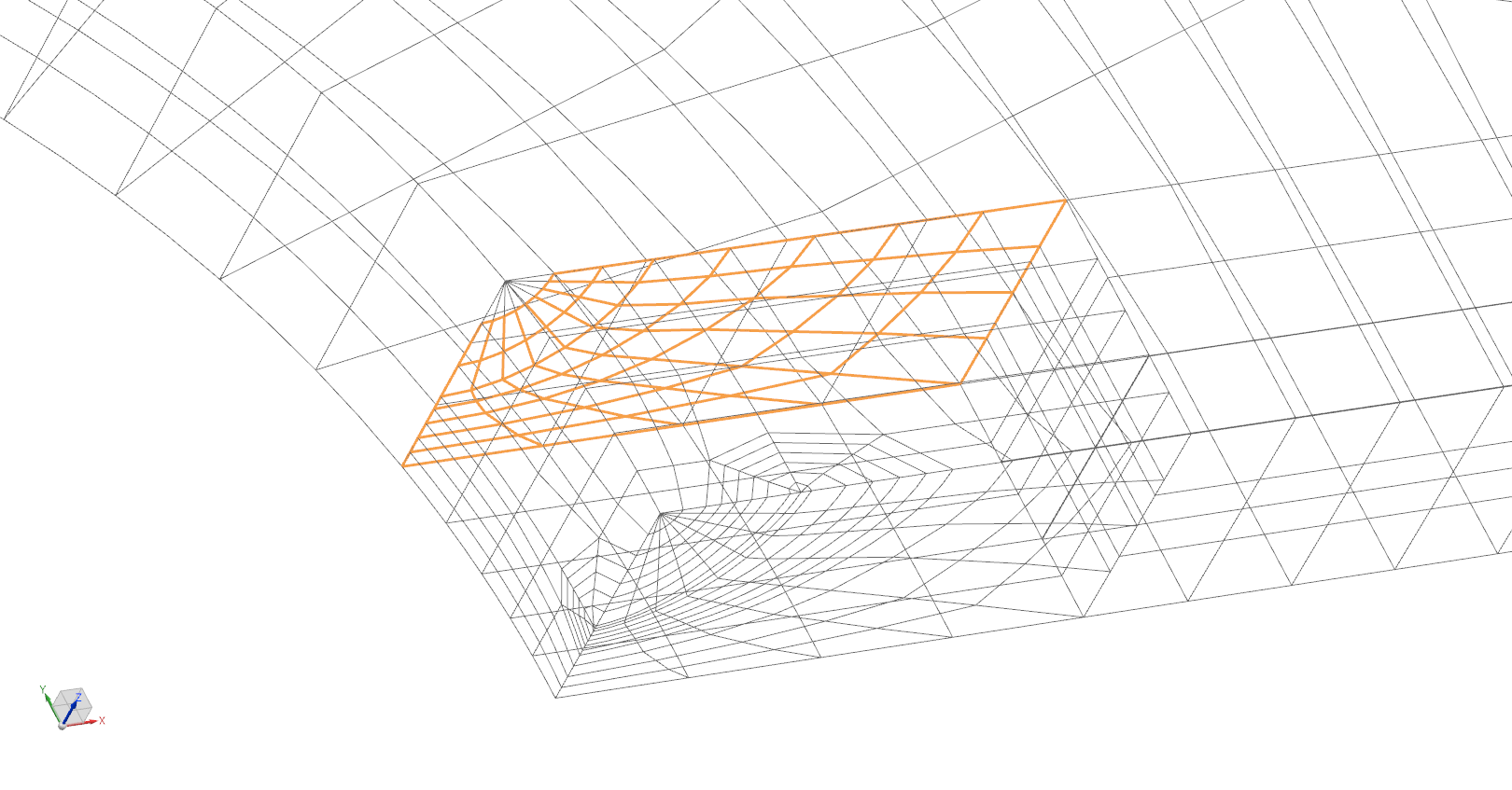
Use of "glue" condition for large crack-blocks in NX Nastran 10 and 11
This issue arises in Zencrack version 7.9-3 (or later) when large corner crack-blocks are used with NX Nastran 10 or 11. This issue is resolved in Nastran 12.0. Full compatibility with this enhancement in NX Nastran is available from Zencrack version 8.2-2.
The method of tying large crack-blocks to the surrounding mesh region uses surfaces and a glue definition. In Nastran 10 and 11 the glue condition does not support the use of collapsed CHEXA element faces within a glued surface. The analysis will either fail with an error or provide incorrect results.
All of the large corner crack-blocks in the crack-block library contain such collapsed CHEXA faces on the exterior face that lies opposite the crack face. If this face is included in a surface definition Zencrack omits the collapsed element faces in order to prevent an error from Nastran. However, this means that the glue is not fully applied across the surface and an approximation is therefore introduced as a small region is allowed to open up.