- Software
- Zencrack
- What’s New in Zencrack?
Zencrack 7.0
What's New in Zencrack?
Zencrack 7.0
Zencrack version 7.0 was finalised on 23 July 2002
There were many enhancements in Zencrack version 7.0. The major items are listed below.
Keyword input format
The input file may consist of comment lines, keyword lines and data lines. The majority of options have default values and only a minimal amount of "essential" data is needed for a crack growth analysis. For example:
# Sample input file with "#" comment line and "*" keyword lines
*FILES,UNCRACKED=example.inp,OUTPUT=example_out
*OPTIONS,INTERFACE=ABAQUS,FE=FULL,TYPE=FATIGUE
*CRACK FRONT, INITIAL=SIZE
sq103x4.sup
 1 1 2 1.0 1.0
*LOAD SYSTEM,TYPE=CONSTANT AMPLITUDE
 0.0  1.0
*CRACK GROWTH DATA,TYPE=PARIS
 7.75E-13 3.2
*TOLERANCE
 0.5
*END
An option is available to convert input files from earlier version to the new keyword format.
New options for defining crack growth data
Previously only single curve input was available as da/dn vs deltaK or deltaG. New options are available for:
- Paris equation
- Walker equation
- tabular da/dn vs deltaK as function of R (up to 100 curves, 100 points per curve)
- user subroutine to define da/dn.
New options for load definition
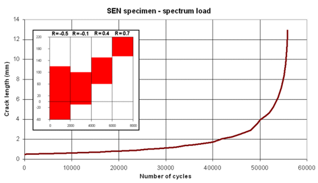
Previously only constant amplitude loading was possible. New options are available for:
- spectrum load history
- superposition of load systems (eg residual stress with cyclic load).
A rainflow counting scheme for random load spectra is also included.


New crack-blocks
In addition to some new crack-blocks, a new approach is available for using "large" crack-blocks. In this approach, surface based tying is used to tie one crack-block to several elements in the rest of the mesh rather than having a strict one-for-one relationship between crack-blocks and uncracked mesh elements.

Definition of threshold and fracture behaviour
Threshold:
- single threshold value independent of R
- threshold as a function of R using the Walker equation
- threshold as a general function of R
- Harter-T method
- user subroutine option
Fracture:
- plane stress and plane strain fracture toughness.
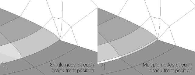
Use of "retained" nodes for the crack tip model
It is now possible to define the use of "retained" or "multiple" nodes at each crack front position. This approach, when used with midside nodes in the collapsed crack front elements, is capable of providing the correct singularity for elastic-plastic fracture mechanics analysis. The default is the use of a single node at each crack front and quarter point nodes suitable for linear elastic fracture mechanics.

Control of the shape and distribution of elements in the crack front region
A number of new options are available to control the shape and distribution of elements in the crack front region. These include:
- extra options for controlling the size of element rings at the crack front
- option to force element edges to be normal to the crack front
- option to allow curved or straight element edges in the crack-blocks.
Improved growth integration scheme
The options for controlling the integration scheme have been improved. An adaptive stepping algorithm is available to control step sizes between f.e. analyses during growth prediction. Generally this provides more accuracy in calculating N for less f.e. runs compared to the previous fixed step algorithm.
Numerical integration scheme
A numerical integration scheme is introduced for the forward predictor integration algorithm to handle cases where a closed form analytical solution is not possible. Such cases include:
- da/dN defined by the user subroutine option
- analysis with residual stress in which case dR/da is non-zero.
Improved control on analysis steps for which j-integrals are extracted (Abaqus interface)
This improved control allows, for example:
- *CONTOUR INTEGRAL frequency to be controlled for each analysis step
- *CONTOUR INTEGRAL requests to be de-activated in a step and re-activated in a later analysis step.
Use of nodal displacements
- use of relative opening displacements to define an "open" or "closed" status at crack front nodes
- use of relative opening displacements to define an "open" or "closed" status at crack face nodes
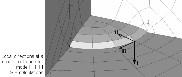
- calculation of Ki, Kii and Kiii from nodal displacements (CTOD).

Crack face contact
Option for automatic inclusion of crack face contact (Abaqus interface only):
- allows crack faces to contact one another under local compressive load
- includes options for specifying Abaqus contact controls.
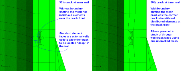
Boundary shifting and large crack growth algorithms
- boundary shifting allows movement of target element boundaries to reduce element distortion in the crack-blocks
- allows analysis of previously impossible crack sizes with one uncracked mesh
- large growth algorithm allows movement of the crack-blocks from one element to the next in the mesh.


Saving f.e. files during a growth analysis
Improved options to save f.e. analysis files during a growth analysis:
- allows f.e. analysis files to be re-numbered and saved for later review or post-processing
- Abaqus files that can be saved include .inp, .dat, .odb and .fil
- Marc files that can be saved include .dat, .out, .t16 and .t19.
User control of output reports and tables
All output tables can be activated or de-activated according to the analysis requirements. Potentially large output tables are "off" by default to prevent the output file from being too large.
Definition of initial crack size
The initial crack size can now be defined using an absolute size. Previously the only option available was the use of a ratio of the required crack size and the corresponding element edge length.
Miscellaneous
- use of dynamic array allocation to reduce memory requirements
- utility program to generate tabular crack growth data from tanh equation data.