
- Software
- Zencrack
- What’s New in Zencrack?
Zencrack 7.7
What's New in Zencrack?
Zencrack 7.7
Zencrack version 7.7 was finalised on 8 February 2011
General
-
A new command line option, -fe, allows parameters to be passed from the
Zencrack command line to the f.e. analysis command line. This can be
used, for example, to override the default setting for the number of
cpus used for the f.e. analysis. The format is such that double quotes
should be used around the parameters e.g.:
runzcr77 -j jobname -fe "cpu=2 datacheck"
- A new option to define split sets is introduced on the SPLIT keyword. The option allows all elements on one side of the split to be listed, followed by all elements on side 2 of the split. It is not necessary for there to be any ordering of pairs of elements on opposite sides of the split within the two lists. This new option significantly reduces input generation time when large split sets of several hundred elements are required.
- The definition of spline (x,y,z) data for user defined initial crack fronts is moved from the CRACK FRONT keyword to a new SPLINE keyword. This allows multiple splines to be defined in an input file with particular splines cross-referenced using a new SPLINE parameter on the CRACK FRONT keyword.
- A report of the crack face area is now generated in the .rep file. This report takes contributions from the crack face parts of the crack-blocks and from split elements if both sides of the crack are modelled and split elements are defined. The report is generated for each crack position in a crack growth analysis.
- New output node sets are created for split nodes with one node set created for each side of each split set. The set names are nSPLITxxxSIDEy (or nSPxxxsx for short format) where xxx=split number, y=side 1 or 2. The side 1 and side 2 definitions are consistent with the split element set side 1 and side 2 definitions. Creation of these sets is controlled as part of the USER parameter on the NODE SETS keyword, with the default being that the sets are created.
- The output of boundary conditions on split nodes was previously done in such a way that multiple definitions of split node boundary conditions could be generated if there were multiple boundary condition data blocks. Each separate boundary condition block now only gets the split node updates that are relevant for that block.
- The saving and renaming of f.e. input and output files is modified to give more consistent renumbering of the input and output files, and to better handle renumbering of files from the last f.e. analysis. In addition, the files from the last f.e. analysis are now only renumbered if that analysis completed successfully.
-
A new option is added to the SAVE keyword to allow retention of the last
successful f.e. files without retaining all the earlier outputs. This
RETAIN LAST parameter can be used with or without the existing FIRST
and STEP parameters. For example:
*SAVE, ODB=YES, FIRST=1, STEP=999, RETAIN LAST=YES
Retains the 001.odb and the final successful .odb (with renumbering).*SAVE, ODB=YES, FIRST=999, RETAIN LAST=YES
Retains only the final successful .odb (with renumbering).
-
New options are included to define how temperatures should be handled
when calculating da/dn for a cycle when multiple results sets are
processed from each f.e. analysis. The available options are:
- Average - Use the average of the actual temperatures at Gmax and Gmin.
- Actual - Use the actual temperature at the Gmax condition.
- Maximum - Use the maximum temperature in the cycle with Gmax and Gmin.
- Mean rate - Use the mean da/dn from the "actual" and "maximum" methods.
-
A new mapping parameter, IN PLANE, is available on the MAPPING keyword.
This allows improved mapping for cases where the crack front has become
relatively distorted in the crack-block.
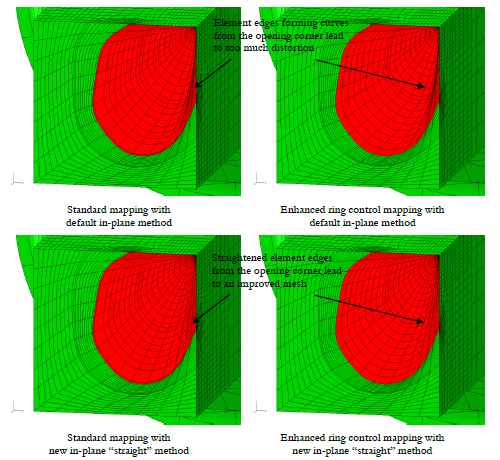
New mapping option IN PLANE
-
Five new user subroutines and two new utility functions are included in this release:
- user_contour - define the combination of contours used to drive the analysis e.g. average of contours 3,4,5
- user_coords_modify - modify nodal coordinates
- user_fixed_relax_nodes - define "fixed" nodes for mesh relaxation
- user_initialise - initialise variables used in other user subroutines
- user_relax_modify - modify mesh relaxation tolerances or de-activate/re-activate mesh relaxation
- utility_crack_front_transfers - extract the number of transfers for a specified crack front
- utility_surround_fix_modify - de-activate/re-activate the surround fix capability
- The user subroutine user_transfer_cf has two arguments added to pass values to the subroutine for the number of crack-block positions that were deemed ready for transfer and the total number of crack-block positions on a crack front. This allows the user to control the transfer condition using a ratio other than the built-in value of 50% of the positions along the front needing to be ready to allow transfer.
- The utility function utility_cords is modified such that the program does not stop if the function is called with a node number that does not exist in the model. If this happens the function now returns a value of -1 and the analysis can continue.
- In an analysis with multiple results sets processed from the f.e. analysis, a new summary table is generated to report the minimum and maximum temperature at each crack front node through all the processed results sets.
- Several new options are introduced on the OUTPUT keyword to allow extra control over the data generated in the .rep file.
- The number of temperature levels for definition of temperature dependent crack growth data is increased form 10 to 100.
- The maximum value for the number of relaxation iterations, SmoothIter, on the RELAX keyword is increased from 100 to 10000.
- The maximum number of results sets that can be processed from a finite element analysis is increased from 1000 to 1500.
- The .shp file is no longer retained at the end of an "initial crack only" analysis.
- GPa and psi units have been added to the unit conversion utility which is included with the documentation (FMunitconversion.htm).
- As an on-going activity with each release we constantly try to improve error and warning messages. In this release many changes have been made to add new warnings and to improve existing warning and error output.
Abaqus interface
-
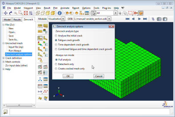
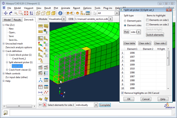
A completely integrated plug-in system is provided for Abaqus/CAE (and
Abaqus/Viewer), replacing the three independent plug-ins provided in
Zencrack 7.6. The new capability takes the form of a "Zencrack tab" with
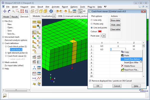
a tree structure, as shown in the example screenshots below.The key features of the new capability are:
- Ability to read an existing zcr file.
- Ability to define a complete zcr file ready for a Zencrack analysis.
- Picking methods for all options in the zcr file that require individual or lists of node or element data.
- Colour-coded highlighting including selected crack faces, crack-blocks, split elements and crack front splines.
- Use of the crack front spline viewer to help during model partitioning at the pre-processing stage.
- The plug-ins are available for nodelocked and network licensing.
- Warnings about possible hourglassing are now generated in the .rep file if crack-block elements are type C3D8R or C3D20R. The analysis proceeds, but it is the responsibility of the user to check deformed mesh plots for hourglassing.
- If T-stress values are requested they are now extracted from the Abaqus analysis and reported in the .rep file. They can also be processed by the PROCESS post-processing program.
- All contour integral requests in the Abaqus input file now include the SYMM parameter if only one side of the crack front is modelled. In previous versions of Zencrack this was not the case and instead Zencrack applied a factor of 2 when processing the results. The revised method removes a potential cause of confusion.
-
Two enhancements are made for the application of symmetry boundary
conditions when the crack front transfer capability allows the
crack-blocks to move across the symmetry plane:
- The removal of symmetry constraints on the crack face as the crack transfers is now supported for types boundary condition types XSYMM, YSYMM or ZSYMM in addition to the existing support for explicit degrees of freedom.
- The symmetry condition can now use a node set whereas in earlier versions the nodes on the symmetry plane had to be listed explicitly for correct removal of boundary constraints as the crack advanced.
-
In Zencrack 7.6 there were two subroutines supplied for extracting
results for the Abaqus .fil file - one for J-integral analysis and one
for Ct-integral analysis. These are now combined into a single
subroutine, zcr-fil.for. The subroutine is further improved as follows:
- In Zencrack 7.6 the increment times extracted from Abaqus are approximate due to the lack of precision in the values being read from the .sta file. Now, when the zcr-fil subroutine is used, the step and total time are obtained more accurately via the fil file. If the zcr-fil subroutine is not used then the behaviour is the same as before and the values in the rep file may be slightly rounded ones.
- The cross-referencing of step and increment numbers and times to the analysis results sets is made more robust for cases with multiple steps and increments when the zcr-fil subroutine is used.
- The file that transfers data from Zencrack to the subroutine is now named with a job-dependent name rather than a fixed name (previously deltau.val, now jobname.val).
- T-stress values can now be extracted from the .fil file into the Zencrack .rep file.
- The default for the maximum number of crack face nodes that can be processed by the subroutine is increased from 5000 to 10000 (parameter nnodedispMAX). This, and other parameters, can be modified in the subroutine file for individual large jobs if required.
-
When crack face surfaces are generated using the CONTACT keyword, the
split elements of any split set are now only added to one set of
surfaces if there are multiple crack fronts connected to the split set.
The split set elements are added to the surface for the lowest numbered
crack front connected to the split. Previously the split elements were
added to every crack front connected to the split. If more that one
crack front is connected to a split set:
- this change prevents overlap (i.e. multiple definition) of split element surface regions with a surface definition.
- to generate a single crack face surface for the complete crack face
the user must manually create a surface that combines the ones generated
by Zencrack e.g.
total surface = ( crack front 1 surface + split set ) + crack front 2 surface + crack front 3 surface etc
- Zencrack now recognises GEN as an abbreviation of GENERATE when processing Abaqus *ELSET and *NSET options.
Ansys interface
-
Improved support is now available for the Ansys uncracked mesh. This
makes creation of the uncracked mesh much more straightforward. Ansys
supports several different input formats for some types of data, such as
nodes and elements. To cater for these possibilities, Zencrack
incorporates a converter that may convert the supplied uncracked mesh
into a new file with certain data lines written in a modified format.
This process is transparent to the user and takes place when the
Zencrack analysis runs. If a conversion is required and is successful, a
.cnv file will be created for the new uncracked mesh.If the conversion encounters formats that are not supported by the
converter the original uncracked mesh should be read into
Ansys/Mechanical APDL and a new file created using the CDWRITE option
with the BLOCKED parameter e.g.:
CDWRITE, , Filename, Extension, , , , blocked
The .zcr file should then be modified to reference this new uncracked mesh file.Uncracked model data contained in Ansys database (.db) files is supported by using the Ansys CDWRITE option, as above. This approach can also be used for files originally created using Ansys workbench. If a third party pre-processor produces a file that Zencrack does not accept, then the procedure of reading the file in to Ansys and creating a new version with the CDWRITE command should be used.
- The sign of J-integral output from Ansys 11 and 12 was generally negative for "opening" cracks. Zencrack 7.6 made allowance for this and changed the sign. In Ansys 13 the basic Ansys output now has a positive sign where it was negative in earlier releases. Zencrack 7.7 supports all Ansys versions and correctly accounts for this sign issue provided that the settings in the runzcr77 file for ZCRANSYS and ZCRANSYSVER are correct.
-
The automatic conversion of legacy element types 45 and 95 to 185 and
186 is modified slightly in this release. The rules for changing the
element type are:
- any SOLID95 or SOLID45 element types are converted to SOLID186 or SOLID185 regardless of whether the "solid" part of the element name is upper, lower or mixed case
- any SOLID95 or SOLID45 element types defined by only their numbers (i.e. 95 or 45) are not changed.
Utility program PROCESS
The process post-processor has several changes:
-
As well as extracting values at specific crack front nodes, it is now possible to extract results at:
- intersection of each crack front with a plane (including multiple intersections if appropriate). If there are multiple crack fronts, only one plane may be specified.
- a specified parametric position, s, along the crack front (taken as
s=0 from end 1 to s=1 at end 2). If there are multiple crack fronts,
the value of s can differ for each crack.
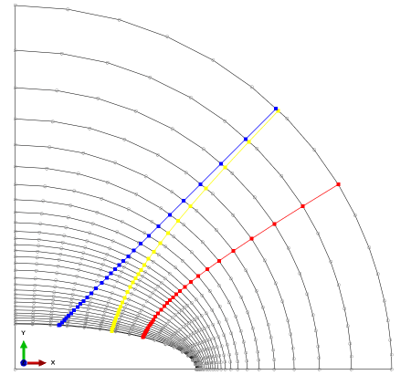
Process the "mid" node position (red line - old option). Process at a position (s=0.5 in this example) along each crack front (yellow line - new option). Process at a plane intersection along each crack front (blue line - new option).
- Some output values have extra precision to allow for the new plane and distance interpolation options.
- A summary of the maximum Ki on each crack front is reported to the screen regardless of what was requested for output to the .csv file.
- Processing of Abaqus T-stress values is supported.
- The output for the final integration step is now always included, regardless of how the analysis terminated.
Utility program 3DMESH
The 3dmesh post-processor has one change:
- For the Abaqus output option an extra file is created. This is a python script file that allows the crack front profiles to be imported into an Abaqus/CAE model as a set of wire splines.
Finas interface
- No longer supported.