
- Software
- Zencrack
- What’s New in Zencrack?
Zencrack 8.3-1
What's New in Zencrack?
Zencrack 8.3-1
Zencrack version 8.3-1 was finalised on 6 July 2018
The main change in this release is an update to the rendering engine that provides mesh and results representation in the Zencrack GUI. This change brings a number of benefits including:
- Significantly faster import of meshes to the GUI.
- Reduced memory requirement.
- General enhancements in the rendering of meshes and results.
Rendering improvements
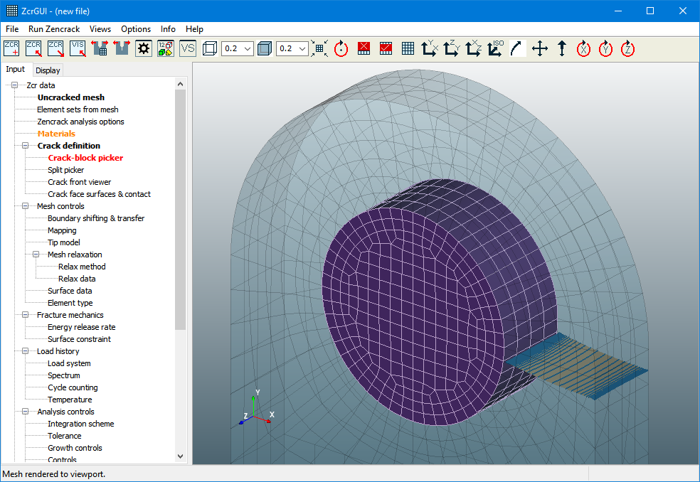
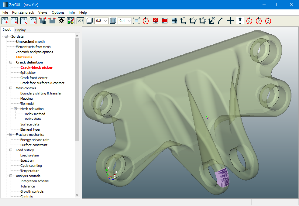
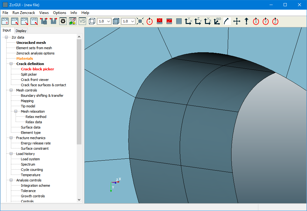
Rendering of mesh fills with or without opacity is improved.
- Mesh fills are smoother across curved surfaces.
- Shading is now maintained when fill opacity is activated.
The Views drop-down menu is modified with updated and new rendering options.
- The edge methods available are now "feature", "external" and "all". The previous option "none" is available by using the toolbar edge toggle icon to turn edges off.
- Two new triads are available, located at the global origin of the mesh and at the current rotate/zoom point. These triads, and the standard mesh viewport triad can be toggled on and off.
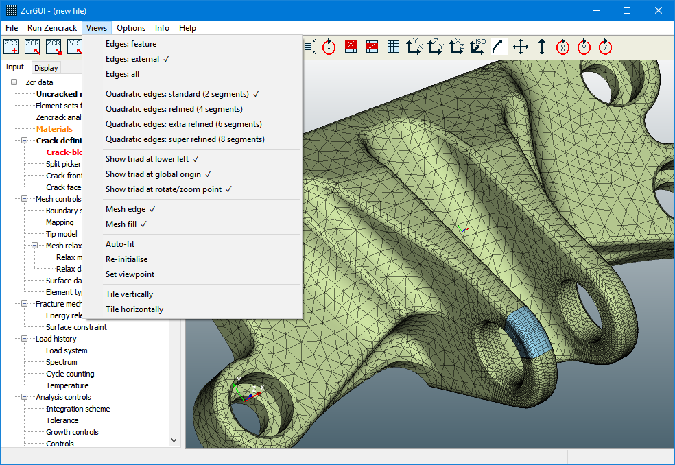
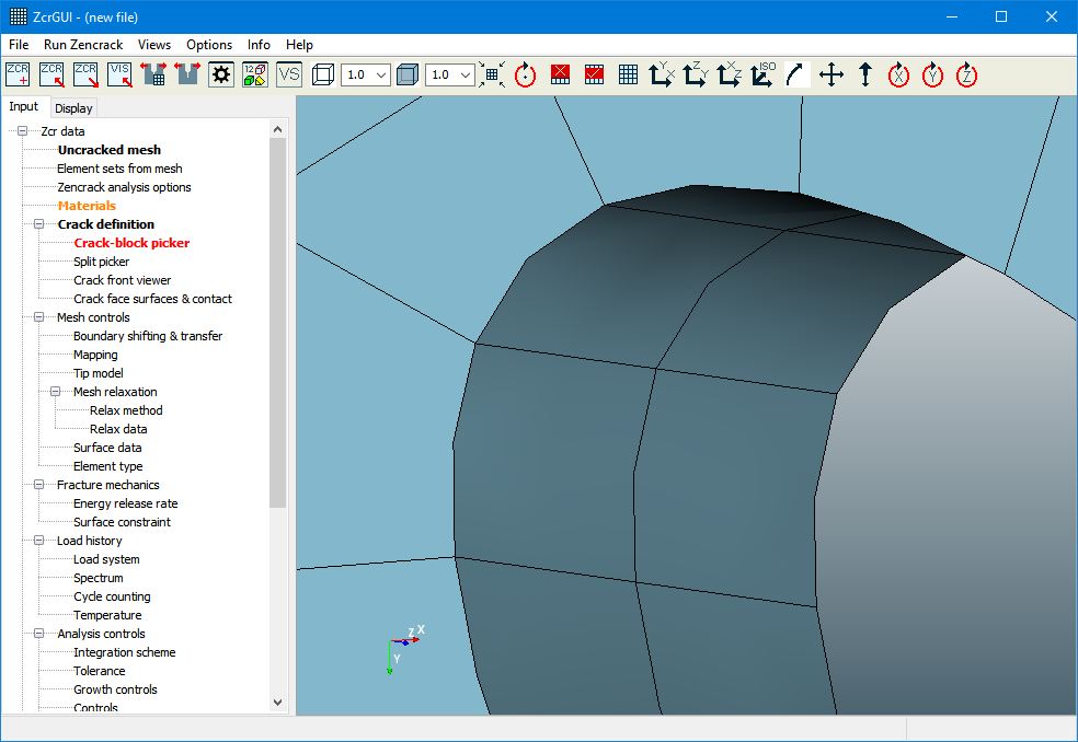
- New options are available to render quadratic element edges in more detail. The default is the same as in previous versions - two linear segments are used per edge. This may optionally be changed to 4, 6 or 8 linear segments. For most models 4 segments provides sufficient improvement in the representation without the additional rendering overhead of 6 or 8 segments. Note that changing the edge settings also means that the mesh fills are rendered more smoothly for curved element faces.
The rendering of points and labels is improved
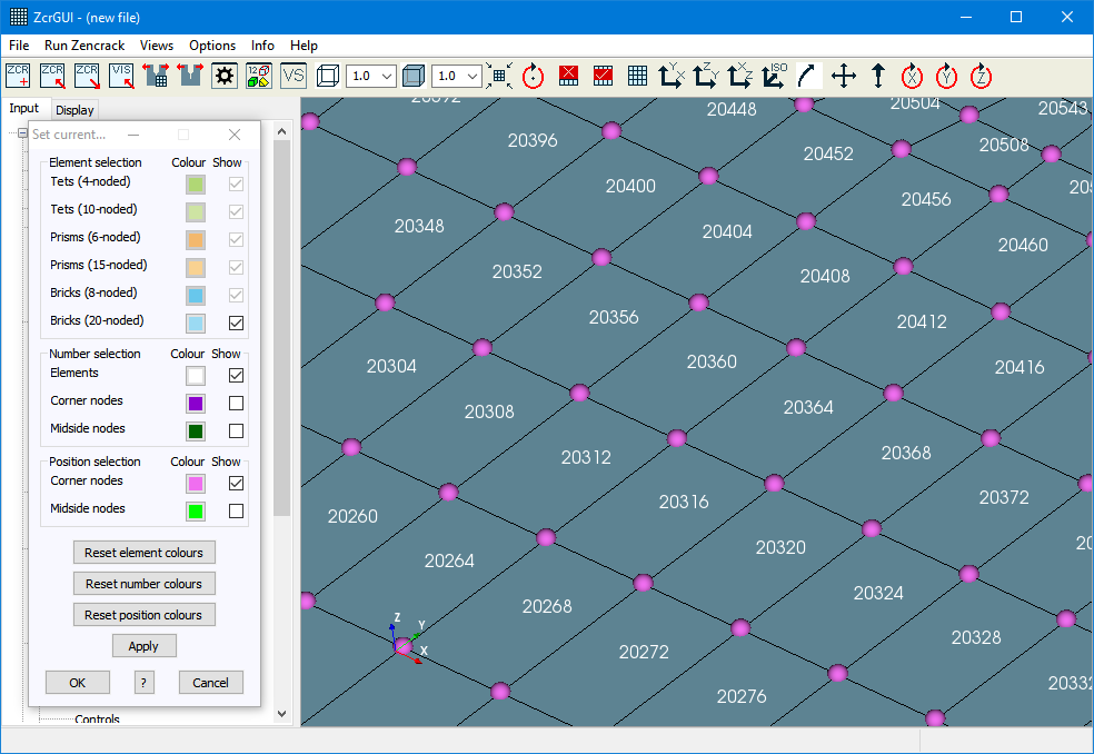
- Element and node labels now produce a less cluttered display than previously.
- Points (i.e. node markers, spline points and points on crack front profiles) can now be rendered as 3D light-enabled spheres or as simple point markers.

Updated "Settings" options
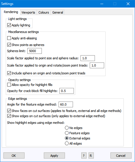
The Meshes tab on the Settings screen is replaced by a Rendering tab. Some previous options are removed and new ones are added:
- Option to apply anti-aliasing.
- Option to show points as spheres. Points are markers for node positions, points along crack front (Input tab) splines, points along general (Display tab) splines and points on the crack profiles of results data.
- For points that are markers for node positions on a mesh the sphere size is an absolute size calculated from mesh parameters. A scale factor can be applied to increase or decrease the default sphere size. The same scale factor can be used if points are shown with the simpler non-sphere representation. In this case the point size is an absolute size is pixels.
- The previous option that allowed the use of opacity on fills of for selections is extended to allow the use of opacity for any type of mesh highlight. Highlights are: Selections, Element sets, Relaxation region, Split sets.
- The crack front highlights in the crack-block picker are controlled by a separate opacity setting as these highlight are usually more useful if shown with opacity turned on.
- The method used to show highlight edges can be specified to be different from edge method used for the main mesh representation.
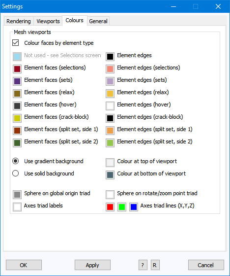
The Colours tab on the Settings screen is updated to allow some additional control overs colours:
- Mesh viewport backgrounds may now be defined with a linear gradient.
- By default, mesh fills are now colour coded by element type e.g. to differentiate linear hex, quadratic hex, linear tet etc. This colouring is defined on the Selections screen. This option can be turned off on the Colours tab with all element type fills then being rendered in the same colour.
- Colours of edges and fills may be defined for the various highlight types.
- Colours applied to axes lines may now be defined separately for the x, y and z directions.
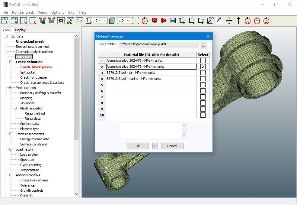
Material export and import
In order to allow the re-use of material data, Export and Import options are now available on the Materials entry on the Input tab.
These options allow existing material definitions in the Input tab to be saved to a folder or to have existing materials from a folder loaded into the current set of input data.
Rendering speed
There are a number of options that control the way in which a mesh is rendered in a mesh viewport. There are some trade-offs between rendering quality and speed which may affect performance when a very large number of entities are displayed. The following are noted:
- Using a mesh edge opacity setting of less than 1 reduces rendering performance for each re-draw of the mesh.
- Using a quadratic edge sub-division of 4, 6 or 8 reduces the rendering performance each time the displayed mesh is changed e.g. when elements are selected or removed.
- When a large number of points are rendered, displaying points as spheres is slower than displaying points as points.
Holding down the Ctrl key before starting a model rotate/zoom/pan sets mesh edges to full opacity during the mesh motion if the opacity is set to less than 1. This can improve rendering speed for very large models.
Holding down the Shift key before starting a model rotate/zoom/pan turns off mesh edges during the mesh motion. This can improve rendering speed for very large models.