
- Software
- Zencrack
- Technical
- Finite Elements & Fracture Mechanics
Energy Release Rate and J-Integral
Finite Elements & Fracture Mechanics
Energy Release Rate and J-Integral
Note: In a Zencrack analysis the j-integral is always calculated (if available in the interfaced f.e. code) and is the default method for providing fracture mechanics parameters to drive crack growth calculations. All of the required input data for the j-integral option in the interfaced f.e. code is created by Zencrack.
The energy release rate and the more general j-integral are fracture mechanics parameters that can be calculated as a post processing exercise following a finite element analysis. Abaqus/Standard, Ansys and Simcenter Nastran all have a capability to allow calculation of these parameters. The input data for these calculations is the specification of one or more virtual crack extensions. The f.e. code returns the energy release rate or j-integral value associated with this virtual crack extension.
If there are multiple loads steps in the f.e. analysis, for example due to the application of a thermal transient, then results for each step are processed giving the variation of j-integral through the load history.
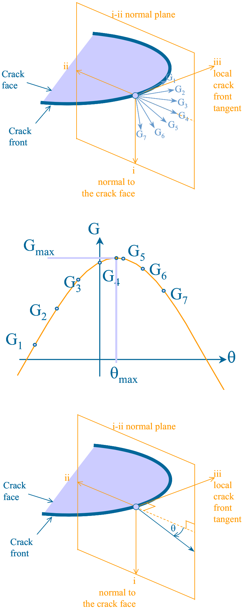
The schematic shows a fan of seven virtual crack extensions within the normal plane at a crack front node. These extensions return energy release rate values denoted here by G1 to G7. When plotted as a function of angle around the crack tip, it is possible to extract the angle at which the maximum energy release rate occurs and the magnitude of this value, denoted by Thetamax and Gmax respectively. In a crack growth analysis the Gmax and Thetamax terms are calculated by Zencrack and used during crack growth integration.
For a 3D crack front the amount of data required to specify the energy release rate calculations can be considerable. The processing of the results also requires a certain amount of effort. Zencrack removes the manual effort involved in these tasks by automatically creating the input and processing the subsequent results after completion of the finite element analysis. The Gmax term and a crack growth direction vector are reported for each node along the crack front.
The energy release rate is calculated for a specified number of "contours". These contours relate to the number of rings of elements around the crack front in the focused meshes of the crack-blocks. Within the Zencrack input the user can control the calculated number of contours and the way in which the results should be used to drive a crack growth analysis. Results for all calculated contours are extracted and reported in the Zencrack output files to allow checking for path dependency.
For Abaqus and Ansys interfaces the interaction integral calculations for stress intensity factors, Ct-integral for creep and the T-stress integral may also be requested. The input data for these options is created automatically using similar contour-based crack extension input as used for the j-integral.
Technical
Finite Elements & Fracture Mechanics
More in this category