- Software
- Zencrack
- What’s New in Zencrack?
Zencrack 7.5
What's New in Zencrack?
Zencrack 7.5
Zencrack version 7.5 was finalised on 12 July 2007
General
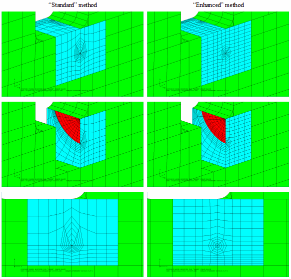
- A new "enhanced ring control" mapping option for crack-blocks has
been introduced. This method attempts to keep the crack front element
rings as close as possible to circular. The enhanced method is
particularly suited to cases where the target element is distorted. In
previous releases extreme distortion of the target elements may have
meant that results were unacceptable. The new mapping method allows
analysis to be completed reliably where it would previously not have
been possible.
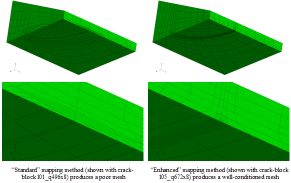
Enhanced ring control - The enhanced ring control method also produces better meshes as the crack moves away from the ideal size within the crack-block.
Enhanced ring control - Two new methods are available for cases when a complex load cycle is modelled by analysing multiple increments through the cycle. In such cases it may not be possible in advance to specify which load increments produce the minimum and maximum energy release rates. Indeed, the critical load increment may be different from one crack front node to the next. An option is now available to search through all result sets for minimum and maximum energy release rate conditions for each crack front node. In this type of search scenario the loading is likely to be non-proportional through the load cycle i.e. the energy release rate magnitude and direction are changing through the cycle. The search method identifies the range for crack growth calculations, but not the direction. An option of taking a weighted average direction across all result sets is available.
- An "automatic split" option is introduced to allow cracks to be
generated in some configurations that were previously difficult to work
with. This option, aimed at through crack geometries, allows edges that
cannot be split using the face-based *SPLIT option to be separated
without any user input. Two examples where this situation may arise are
shown here.
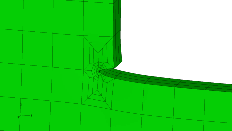
Auto-split example 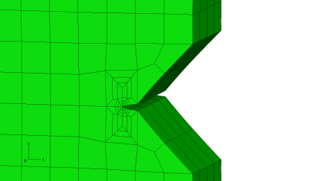
Auto-split example - Increased flexibility is available on the SAVE keyword for specifying the save parameters for different file types. This allows, for example, the main f.e. results file to be saved every 5th step but the cracked mesh input file to be saved every step. This can have significant benefits on disk space usage for large models in a crack growth analysis.
- The control and generation of crack related node and elements has
been standardised across the Abaqus, Ansys and Marc interfaces. Options
are added to turn on or off the various types of sets that can be
created. In addition, some new sets are available. These changes enhance
the possibilities available while post-processing the cracked mesh.
- New element sets are available that combine all crack-blocks on each side of the crack front. This means that side 1 or side 2 of the crack can be selected via single sets.
- The sets for split elements that existed in v7.4a are divided into separate sets for each side of the crack face.
- A new element set option is added to allow creation of element sets on the outer faces of all crack-blocks.
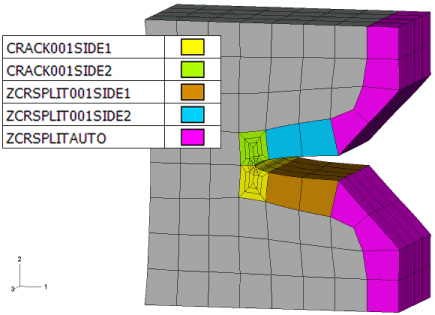
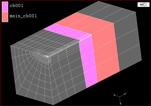
Element sets created on crack-blocks
Crack-block library
- The crack-block st12x1 that was released with Zencrack 7.4a is now
moved into a new "family" and becomes s05_t12x1. A new corner
crack-block s05_q24x2 is included as the other member of this
crack-block family.
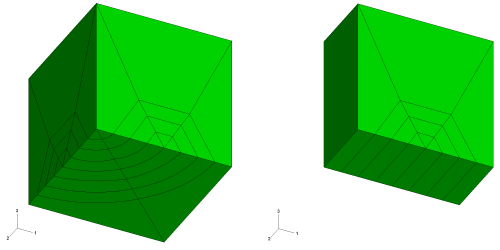
New crack-blocks - Two new large crack-block families are available with this release.
They are families l05 and l06. The crack-blocks in family l06 (shown
below) are 2x2x2 refinements of crack-blocks in family l05. These new
crack-blocks are intended to take full advantage of the new mapping
options available via the enhanced ring control methodology. Family l05
also contains three extra crack-blocks that have additional
sub-divisions along the crack front.
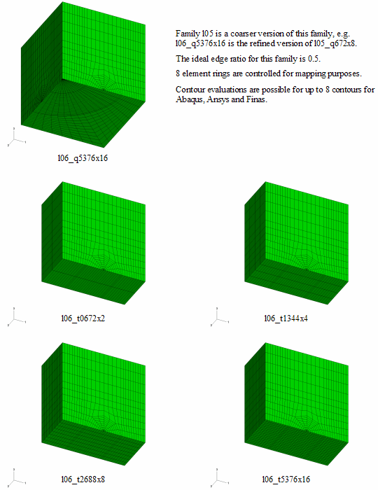
Crack-block family l06
Abaqus interface
- Shear load types TRSHRn and TRSHRnNU are updated on the outer surfaces of the crack-blocks if these loads are applied to the target crack-block elements.
Ansys interface
- The Ansys interface is upgraded to allow use of the j-integral capability that is now available in Ansys. Although introduced in Ansys 11.0, the calculation and processing of j-integrals by Zencrack requires Ansys 11.0SP1 (or later). The addition of this capability allows users to choose whether a crack growth analysis is based on results derived from j-integral evaluation or from stress intensity factors derived from nodal displacements. This choice is made on the ENERGY RELEASE RATE keyword. All generation and processing of j-integral data is handled fully automatically and allows for non-planar crack development.
- The handling of multiple sets of load increments from an Ansys (non-linear) analysis has been improved.
- The handling of thermal-stress analysis in the Ansys interface has been improved.
Finas interface
- Support is added for Finas user subroutines.
Marc interface
- Processing of multiple load increments from the f.e. analysis is now possible. This means that the full scope of the Zencrack load system methodology is available.
- The location of the Marc executable can be defined in the runzcr75 script file that is used to run Zencrack. The *EXE option still exists to allow the global setting to be overridden for individual jobs. Direct specification of Marc user subroutines via the Zencrack input file is also available. An option is included for whether or not to save the generated Marc executable.
- An improved method is introduced to allow large crack-blocks to be used with the Marc interface. The method is based on the automatic creation of element sets for the outer face of each crack-block by Zencrack in conjunction with glued contact in Marc.
