
- Software
- Zencrack
- What’s New in Zencrack?
Zencrack 7.8-1
What's New in Zencrack?
Zencrack 7.8-1
Zencrack version 7.8-1 was finalised on 28 June 2012
This release introduces a new load system that is able to process complex thermo-mechanical load cycles.
General
Fracture mechanics / engineering enhancements
The major engineering enhancement in this release is the addition of a new type of load system definition for crack growth calculation. This "full cycle" load system is based on detailed analysis of a complete load cycle in the finite element analysis, for example a full flight cycle, manoeuvre to manoeuvre cycle or any general cycle which repeats periodically. This option has been implemented as a result of development work carried out during a three year Technology Strategy Board project which ended in December 2011. The project, titled DISPLACE (Developing Improved Service Propagation Lives in Arduous Cyclic Environments), was led by a major aerospace engine manufacturer and included industrial and academic input with significant thermo-mechanical testing in addition to implementation of new techniques into Zencrack. Some of the early developments during this project were already included in Zencrack 7.7 and this release includes the new full cycle capability.
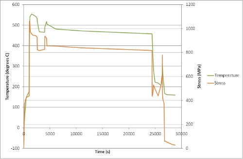
Energy release rates and stress intensity factors are calculated at each crack front node throughout the complete load cycle and are used to drive the crack growth calculations over the next N integrated load cycles with the option of including time dependent crack growth effects in addition to fatigue. This capability is of particular importance in high temperature applications such as aerospace engines where the influence of time dependent crack growth can be significant. The capability includes:
- Fatigue-only, time-only or combined fatigue-time crack growth analysis.
- Fatigue options for inclusion of :
- major cycle only.
- major cycle plus exchange rate (where the exchange rate accounts for minor cycle effect without explicit inclusion of the minor cycles).
- major and minor cycles (i.e. rainflow count is performed on the extracted K history).
- Full thermo-mechanical crack growth analysis with out-of-phase stress and temperature histories.
- Optional application of a shakedown adjustment factor to account for reduction in peak stress due to elastic shakedown.
To support this new capability a number of other enhancements are included:
- New time dependent crack growth law with temperature dependency.
This law, named the COMET crack growth law, includes the combined
synergetic effects of creep, oxidation, microstructure, environment and
temperature:
COMET crack growth law - New options to control the behaviour of the Paris and Walker fatigue crack growth laws for negative stress ratios.
- New option for interpolation between temperature dependent crack growth data.
- Options to include unit conversion factors for some types of crack growth data.
- Option to include mixed temperature units in the Zencrack input file and the finite element analysis.
- Improved control of detailed integration output and an increase in the number of quantities available if detailed integration output is requested.
- Increase in the maximum number of results sets that can be processed from a finite element analysis from 1500 to 5000.
- Increased precision in some of the output values in the .rep file.
Output and post-processing
New node sets can be created in the cracked mesh files to help visualise the active relaxation region. These sets are created if *NODE SETS, INTERNAL=YES is used. For example, the highlighted nodes in the above figure showing the relaxation radius are the new node set zcrRelaxNodesMove.
The detailed integration output generated in the .bk1 and/or .bk2 files is improved as follows:
- separate output files are generated for each crack front node
- header information is included in the files
- the available data is extended to cater for the improved fatigue-time analysis capability
- options on the *OUTPUT keyword give considerable control over which crack front nodes have this detailed integration output generated
- options on the *OUTPUT keyword allow control over which part of the load / time history is reported in the detailed integration files
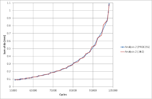
The utils\examples folder of the Zencrack installation contains a sample .bk2 file and an Excel template file. Any .bk2 file can be pasted into the "data" sheet of the template file to automatically generate key graphs e.g. a vs N.
An example of the benefit of this detailed output for a fatigue analysis with blocked spectrum loading is shown below. The output from the PROCESS utility gives data at the finite element analysis positions whereas the detailed (.bk2) integration output clearly shows a stepped response due to the changing growth rate as different blocks of cycles are integrated.
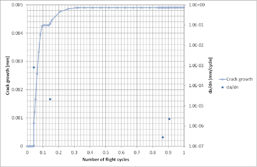
This detailed integration output in a combined fatigue-time analysis allows development of a very clear understanding of how da/dn and da/dt effects contribute to the growth during a single complex load cycle. The example below shows growth through a single flight cycle with markers indicating the position of the four fatigue cycles, identified by a rainflow count, within this particular flight cycle.
Modelling enhancements
An initial read of the uncracked mesh data has been introduced to allow extraction of node and element data before the Zencrack input file is processed. This creates the possibility of new options within the definition of the initial crack location:
- If a single through crack-block is defined, Zencrack will search for
adjacent connected elements and apply the same crack-block type for
those connected elements. This means that if a crack front requires the
same crack-block type for all crack-blocks, it is only necessary to
define one crack-block even if the final crack front contains several
hundred crack-blocks.
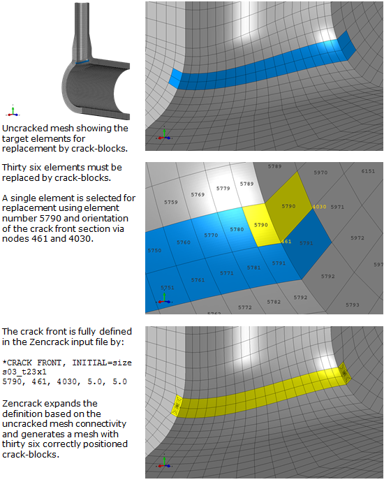
Example of crack-block expansion - If a single split pair is defined, Zencrack will search for adjacent
connected elements to automatically identify the full split set
definition. An example is shown below.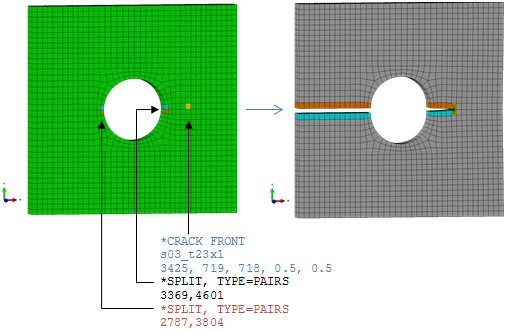
Example of split pair and crack-block expansion (and a split pair not connected to a crack front)
Abaqus interface
The Abaqus RESIDUAL STRESS STEP parameter on *CONTOUR INTEGRAL, introduced in Abaqus 6.11, is now supported. Input for this option can be defined via an optional third item of the data line when the Zencrack STEPS parameter is used on *ENERGY RELEASE RATE.
Extraction of results from the Abaqus .odb file is now possible using the RESULTS=ODB option on the *ENERGY RELEASE RATE keyword. This method provides better precision than the extraction of data from the .dat file (which remains the default), without the need for a Fortran compiler which is required when extracting results from the .fil file. Although the .dat extraction has been retained as the default in this release, users are encouraged to extract results from the .odb or .fil files.
Changes have been made to the Abaqus/CAE plug-ins to allow use of the new relaxation radius options and for compatibility with Abaqus 6.12. The supplied plug-in files can be used with Abaqus 6.8 or later.
Marc interface
No longer supported.
Ansys interface
A full *RESTART analysis is now possible if solid model commands are found in the uncracked mesh. Solid model Ansys runs are repeated in the restart run, but the "full solution" runs are not - they extract results from a previous analysis as per a normal restart run.
To ensure that the necessary results will be available from the Ansys analysis, Zencrack now inserts OUTRES requests immediately before the SOLVE keyword. In previous versions, any user specified OUTRES options that turned off certain output requests could have meant that data was not available at the end of the analysis.
The BF option containing TEMP is added to the list of options used to signify that temperatures are present in the Ansys analysis.
When processing a CMBLOCK node set, Zencrack is now able to remove nodes from the set after a crack-block transfer if the nodes are on the crack face. This is required in case the set is used for application of boundary constraints (which is the method used by files written from Workbench). This is an extension to the processing of the CMBLOCK option introduced in version 7.7-2.
The processing of ESURF data is modified to allow contribution to the surface from multiple faces of an element. Previously, it was assumed that there would only be one face on an element contributing to an ESURF surface. In addition, the program checks the faces of hex elements to ensure that they are external faces of the currently selected element list before outputting the surface data for the faces. The external face check is not currently implemented for tet elements that may be in the selected element list.
When Workbench creates a file containing a contact definition, it defines parameters tid and cid which are then used on several options related to the contact definition. These parameter are now processed by Zencrack.
If an Ansys run has an element other than 185 or 186 for a crack-block, all contour integral results are set to zero and a warning is issued about the element type.
In previous releases of Zencrack a SAVE option was used in the cracked mesh file to save the .db file. This produced duplicate .db files for the last step of an analysis. This duplicate is no longer generated.