- Software
- Zencrack
- What’s New in Zencrack?
Zencrack 9.0-1
What's New in Zencrack?
Zencrack 9.0-1
Zencrack version 9.0-1 was finalised on 25 January 2022
This version contains a completely new remeshing capability to speed up the creation of meshes containing cracks:
- mesh-independent geometry definition of initial crack with remeshing for the initial crack and subsequent crack growth
- remeshing capability in the Abaqus interface
- all crack-block meshing capabilities from previous Zencrack versions remain available
- available for Windows 10 (Windows 7 and Windows 8 also supported)
Remeshing Capability
A new remeshing capability provides mesh independent crack insertion into an uncracked mesh. This approach simplifies the creation of 3D models containing cracks by using a purely geometric definition of an initial crack.
An existing uncracked mesh can be used "as-is" with, in most cases, no need to perform special partitioning or meshing of the uncracked geometry. This means that, for example, a single uncracked mesh can be used to develop models of significantly different cracks by simply changing the geometric crack definition.
- initial crack and crack growth
- remeshing for analysis of initial crack only
- remeshing for general non-planar 3D crack growth using the existing load system methodologies in Zencrack for fatigue, time dependent and combined fatigue/time crack growth prediction
- geometric definition of an initial crack
- initial crack location is fully independent of the underlying mesh
- the underlying mesh may contain hex or tet elements
- crack at a symmetry plane, surface breaking or fully embedded
- initial crack shape may be straight or elliptic (either full ellipse or elliptic arc)
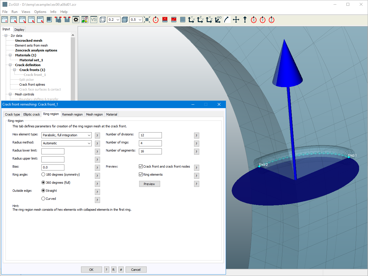
- remeshed region split into hex rings and surrounding tets
- rings of hex elements at the crack front with ring mesh density controlled by the user
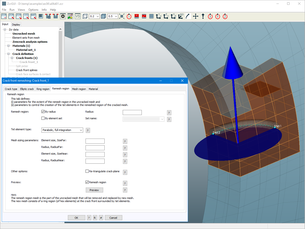
- tet mesh surrounding the rings
- fully automatic calculation of the extent of the remeshed tet region and mesh density within that region (with manual control if desired)
- support for static, thermal and coupled analyses
- update of displacement boundary conditions, pressure loads, surface definitions, film coefficients and temperatures in the remesh region
- optional application of pressure and/or film coefficients to the crack face
The remeshing capability is fully supported in the Zencrack GUI with options to preview various aspects of the initial crack definition, including:
- option to define geometric positional data by picking nodes in the uncracked mesh
- preview of the geometric crack definition
- preview of the hex rings at the crack front
- preview of the remesh region
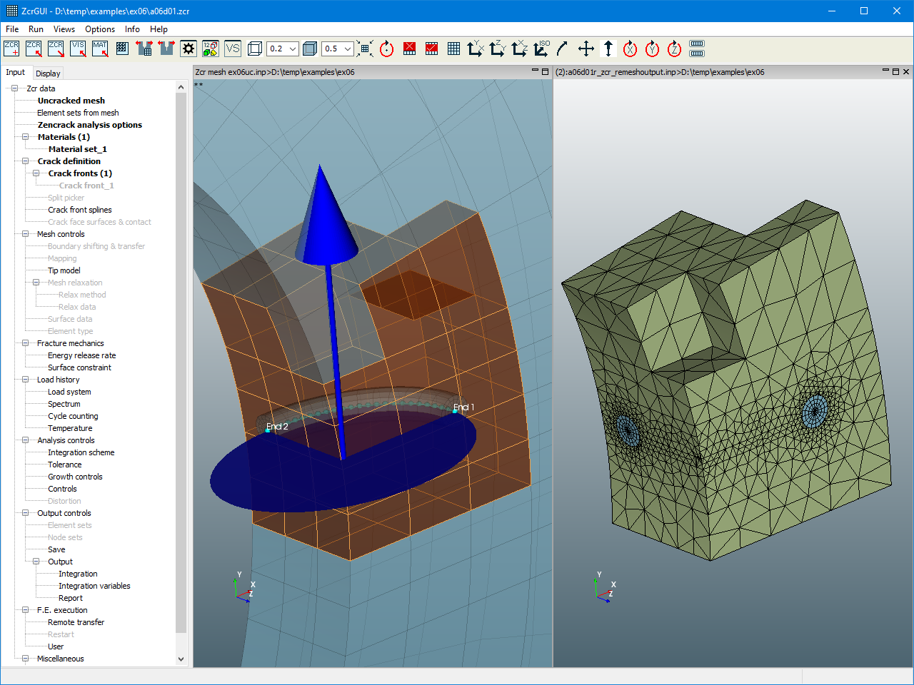
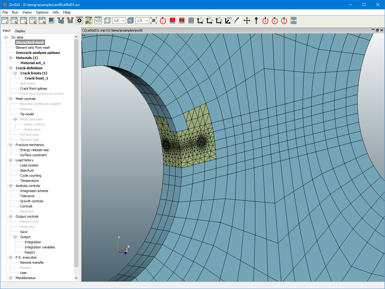
- preview of the remesh region with the crack inserted
Other developments in Zencrack
- Implementation of crack growth direction from stress intensity factors based on the work of Richard et al.
- Ref: H.A.Richard, M.Fulland, M.Sander, Theoretical crack path prediction, Fatigue Fract Engng Mater Struct 28, 3-12, 2005.
- Extension of the processing available for interaction integrals to allow them to be used to drive a crack growth analysis.
- Support for the Ansys option for specifying the auxiliary field solution when calculating interaction integrals: mixed, plane stress or plane strain.
- Re-working of some of the options on the *ENERGY RELEASE RATE keyword to accommodate some of the above changes and to allow future additions.
Changes in the Zencrack GUI
- New input, preview and display options to support the new remeshing capability for crack insertion into an uncracked mesh (see additional examples below).
- Re-working of the Energy Release Rate screen to accommodate the changes described above.
- Improved performance for large meshes (faster import and manipulation).
- Import and optional display of the material regions defined in a mesh.
- Identification of disconnected mesh regions.
- Labelling of profiles when displaying crack growth profile results.
- Labelling of splines (Input Tab crack front splines and Display Tab splines).
- Ability to add multiple meshes into one viewport.
- Ability to display some types of surface definitions (initially to support remeshing previews).
Examples of remeshing - crack growth
This section presents four examples of crack growth prediction, each carried out in a single automated analysis.
Inclined straight starter crack in a 4-point bend specimen with a hole
An initially inclined crack which straightens and grows past the hole. The final animation shows a straight through (not inclined) starter crack located closer to the hole. This deviates towards the hole rather than growing past it.
