- Software
- Zencrack
- What’s New in Zencrack?
Zencrack 9.4-1
What's New in Zencrack?
Zencrack 9.4-1
The base code for Zencrack version 9.4-1 was finalised on 31 May 2024 and released in June 2024
The highlights for this release are:
- Remeshing allows multiple cracks to exist within a remeshed region. This means that cracks that grow towards one another in separate remeshed regions may now grow closer as the separate remesh regions merge into a single region. The ability to include multiple cracks in a single remeshed region also provides an improved capability for analysis of interaction and shielding cases for closely spaced defects.
- For remeshing models the crack surface area is reported to the .rep file and is also available for plotting in the GUI.
- Support is added for remeshing in regions of collapsed brick elements.
- The default file encoding for the GUI is changed to handle a wider range of non-ASCii characters.
Merging of remesh regions
Remeshing now supports merging of remesh regions to allow multiple cracks to exist within a single remeshed region. As in version 9.3-1, separate remesh regions are calculated for each crack front in a model. If any regions touch or overlap they are now merged and redefined as a new region. The merging process is automatic and requires no additional user input.
This means that:
- Multiple cracks whose initial positions are close to one another can be modelled more easily than in earlier versions of Zencrack, allowing better assessment of crack shielding and interaction effects.
- Cracks that start within separate remesh regions may later exist within a single remesh region if they grow towards one another.

Geometric definition of five initial cracks
Cracked mesh with five cracks in two remeshed regions
Cracked mesh (zoomed view)
Cracked mesh (zoomed view, Mises stress in Abaqus/Viewer)
Remeshing improvements and changes
Calculation of crack surface area
The crack surface area is calculated and reported to the .rep file for a remeshing model. The variable is added to the list of x and y variables when creating xy plots in the GUI.
The crack surface area is the summed area of element faces on one side of the crack.
Improved crack face surface definitions
In the initial multi-crack remeshing capability in version 9.3-1, the creation of crack face surfaces in the cracked mesh was limited to a single surface definition that would include contributions from all separate cracks. This meant that, for example, application of pressure load to the crack surface of crack 1 but not to cracks 2 or 3 in a three-crack model was not possible. In version 9.4-1 the crack face surfaces are defined on a per crack basis allowing control over application of pressures and/or film coefficients on individual crack surfaces.
Remeshing regions of collapsed hex elements
If an uncracked mesh contains large regions of collapsed hex elements, the crack position may be defined to exist within the collapsed elements. This was not supported in version 9.0-1 to 9.3-1. The remeshing may still fail if the remeshed region extends from the collapsed elements into a region of normal elements. An error message is reported if this is the case.
Tet element distortion tests
During the remeshing process extra tests are included in version 9.4-1 to reject poorly shaped tet elements using tests that better match those used by Abaqus and Ansys. Previously, the remeshing process only rejected tet elements which failed the Abaqus zero-volume test. Tests are now extended to account for different behaviours in Abaqus and Ansys.
Local .ini files
Local zencrack_gui.ini files were introduced in version 9.2-2. In version 9.4-1 this is extended for command line Zencrack jobs that use remeshing to allow overrides for specific jobs:
- A zencrack_gui.ini file may be included in a job folder alongside the .zcr and uncracked mesh files. This file is used for any command line jobs in that folder.
- A jobname.ini file may be used in the job folder for job with name jobname.zcr. This file is used only for command line execution of jobname.zcr.
- The job folder zencrack_gui.ini takes precedence over any .ini files in the user home folder.
- The jobname.ini file takes precedence over the job folder zencrack_gui.ini file and any .ini files in the user home folder.
- These job folder and job name .ini files are intended for running remeshing cases that require specific settings in the .ini file e.g. the use of the RemeshTrimEnds=Parabolic option.
Zencrack GUI changes
Display of collapsed elements
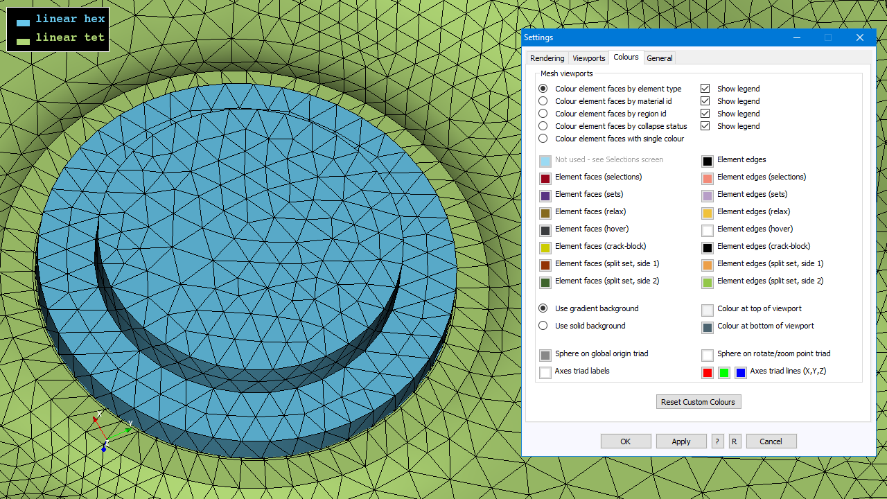
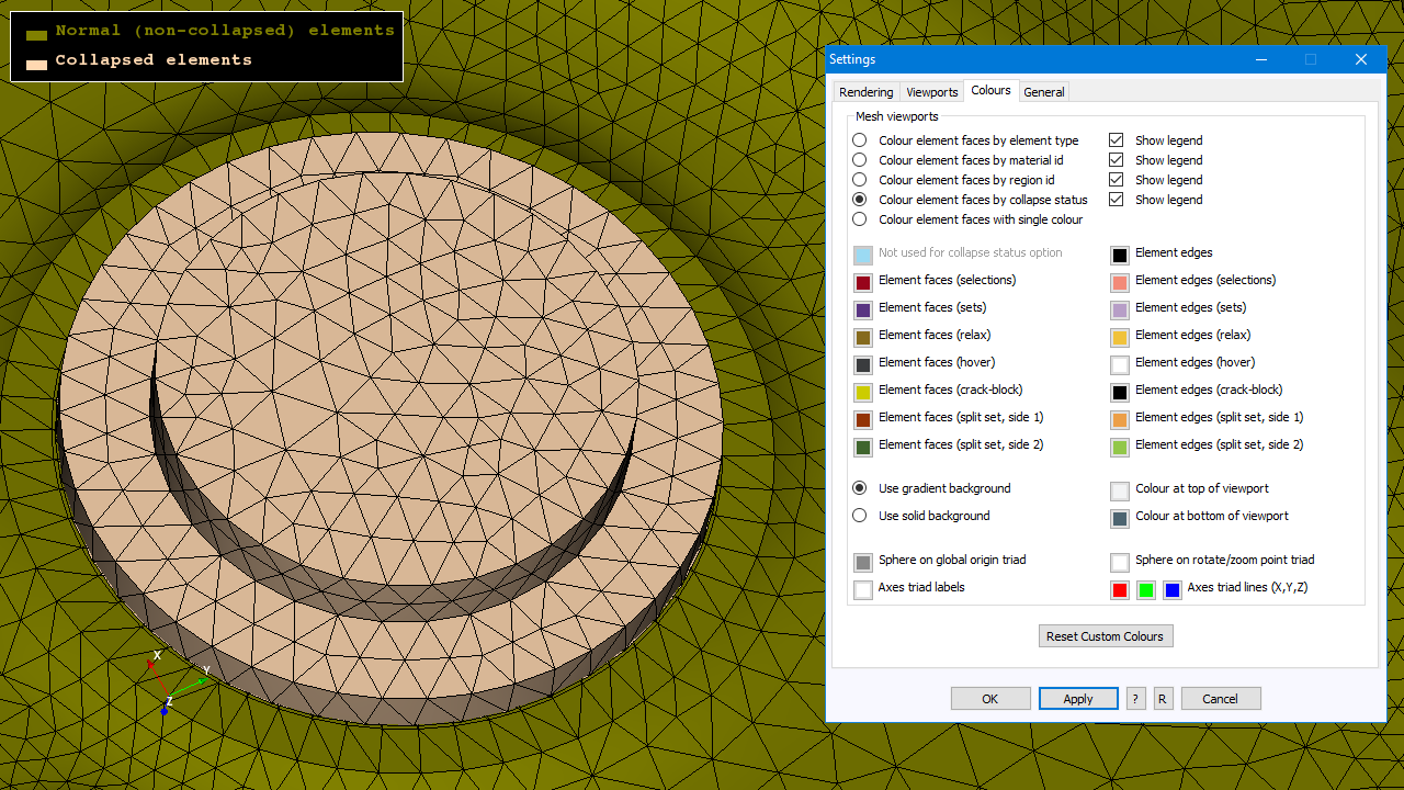
An option to render meshes with 'colour by collapse status' is added to identify regions that are modelled with collapsed hex elements. In the default 'colour by element type' mode it is not always obvious that a mesh contains collapsed hex elements so the option to 'colour by collapse status' helps identify any such regions.
XY plots of crack front coordinates, 'Sum of da' and 'Distance along coordinate path'
In version 9.4-1 there is a change to the way that the Process utility program extracts and reports crack front coordinate positions. This extraction is used to derive data for f.e. snapshot xy plots of coordinate values in the GUI.
From version 9.4-1 the coordinates extracted are those after the integration process and after any redistribution of node positions along a crack front to ensure consistency with the model geometry i.e. the positions analysed in each f.e. model. Previously, the extracted coordinates were the values after the integration process but before redistribution of node positions along a crack front. These positions could lie outside the model bounds e.g. as a crack front transitions around a corner.
Also in version 9.4-1, an alternative definition of 'sum of da' is introduced such that two definitions are provided:
- Integration-based definition: the 'Sum of da' term used up to Zencrack 9.3-1, referenced from 9.4-1 onwards as 'Sum of da (from integration)'.
- Geometric-based definition: 'Sum of da (from f.e. analysis profile points)' which is a geometric definition based on the coordinate positions after adjustment of crack fronts to the model bounds.
XY plots of crack surface area and crack front length
In version 9.4-1 the crack surface area is available for plotting for remeshing models. The variable is added to the list of x and y variables when creating plots.
The crack front length is available for plotting for remeshing and crack-block models. This attribute can be plotted from .rep files created in earlier program versions by opening the .vis file for an existing job in the 9.4-1 GUI and following the normal xy plotting process.
Changes to XY plot screens
The layout of the xy plot screens has been updated for consistency across the different XY plot types.
A new 'reduced variable axis list' is available on all xy plot screens to promote the most important output variables from the full set of variables.
Miscellaneous changes
The default character encoding used when reading files into the GUI is changed to utf-8. Compared to the previous use of the ASCii character set, this reduces the possibility of a character being encountered that is outside the expected encoding. If an out-of-encoding character is encountered, an error is reported and the reading of the file fails. If the need arises, a new setting in the GUI .ini file, [SETTINGS]Encoding, allows a different encoding to be used when opening files.
There are small efficiency gains in reading meshes after an initial conversion has been carried out (i.e. additional information is saved to the binary conversion file to save repeat processing each time that file is read into the GUI).
There are small efficiency gains in parts of the GUI code when processing models with collapsed hex elements.
The behaviour of the colour picker screen has some modifications:
- The Custom Colours entries are blank by default (instead of being filled with a hard coded list of colours).
- Some screens that allow colours to be selected do not have a reset button to enable the colours to be reset to the default values. On those screens the default colours are now inserted onto the last entries of the Custom Colours boxes of the colour picker screen to allow the defaults to be re-selected if they have been changed.
- The Colours tab of the Settings screen includes a new button, Reset Custom Colours, to allow the custom colours on the colour picker screen to be reset.
Other Changes
Abaqus interface
The zcr-odb.py script file used to extract results from the Abaqus .odb file is updated for compatibility with Abaqus 2024 (which uses Python 3 compared to Python 2 in earlier Abaqus releases). Two .py script files are included in the fe_abaqus folder, one for Abaqus 2024 and later versions and one for Abaqus 2023 and earlier versions. Zencrack automatically uses the correct script according to the Abaqus version used for an analysis.
As a result of the change in the Python version for Abaqus 2024, the plug-ins for Abaqus/CAE 2024 require a new set of compiled files. Plugins are no longer supplied for Abaqus 6.9 and earlier. Plug-in folders for three underlying Python versions are described by the relevant Abaqus versions:
- zencrackplugins_6-10_6-13
- zencrackplugins_6-14_2023
- zencrackplugins_2024_onwards
The keyabq.dat file is updated for Abaqus 2024.
One extra significant digit is retained in coordinate values during the mesh conversion process. This can help with calculations related to near-flat tet elements that are close to failing distortion tests.
The surface name introduced in version 9.0-1 for crack face surfaces in a remeshing model, SURFACE_CRACKFACE, is changed to be defined per crack i.e. SURFACE_CRACKFACE_N for crack faces of crack number N. This enables better control of crack face loading in multi-crack models.
Ansys interface
There are some changes to the way that possible overconstraints are handled when creating a mesh. This is to allow for different behaviour observed in Ansys 2024R1 compared to earlier Ansys versions.
The keyans.dat file is updated for Ansys 2024R1.
The status value of the Ansys keyword KEYOPT in keyans.dat is changed from 1 to 0 to enable the keyword to be processed by Zencrack.
One extra significant digit is retained in coordinate values during the mesh conversion process. This can help with calculations related to near-flat tet elements that are close to failing distortion tests.
Ansys crack-block jobs with transition elements had an incorrect pressure update and the possibility that transition elements may be on the wrong faces of the crack-block. These issues are resolved as bug reference zencr552 and zencr554 respectively.
The component name introduced in version 9.1-1 for crack face surfaces in a remeshing model, SURFACE_CRACKFACE_SURF154, is changed to be defined per crack i.e. SURFACE_CRACKFACE_SURF154_N for crack faces of crack number N. This enables better control of crack face loading in multi-crack models. The type ids associated with the crack surface elements are also changed to be dependent upon the crack number.
User subroutine user_dadn_sif
This subroutine previously received displacement based stress intensity factor values, even if the crack growth calculations were driven by a different parameter e.g. j-integral values.
From version 9.4-1 the subroutine can receive displacement based or SIF-integral stress intensity factors if the fatigue crack growth is driven by one of these parameter i.e. if the MAGNITUDE DADN parameter of keyword *ENERGY RELEASE RATE is set to SIF-displacement or SIF-integral. In other cases the subroutine is not allowed, and an alternative subroutine should be used. The arguments for the subroutine are not changed, but the documentation of the subroutine is updated to better describe the data that is passed in and the variations that occur according to choice of load system and integration scheme.
Licensing
The Windows installer for the RLM license server is modified to allow creation of a Windows service to run the license server. This is beneficial for new installations but if the current version, 14.1.3, of the license server is already installed from a previous Zencrack version, there is no need to use the latest installer file as the license server itself is not changed in this release.
Information about ports and firewall requirements for the license server is added to the Installation And Execution Manual.
Configuration file output_codes.dat
The output_codes.dat file is updated to add new variable definitions and to add options for the reduced variable axis list in the GUI. There are also some changes to variable names (for consistency with the changes in the Process utility program).
Configuration file zencrack_gui.ini
From version 9.4-1 all entries in the zencrack_gui.ini file are commented out so that default values are used. This also clarifies the section at the start of the GUI log file which lists entries obtained from the .ini file i.e. it is now easier to identify any non-default values that have been set in the .ini file.
New entry 'Encoding' in the zencrack_gui.ini file allows the file encoding when opening files to be modified.
Documentation
A new remeshing example is added to the Examples: Step-by-step Manual.
Utility program PROCESS
The PROCESS program is updated in version 9.4-1 to extract the crack front length (for remeshing and crack-block models) and the crack surface area (for remeshing models). Some existing columns have their titles changed for clarity and, in addition to crack front length and surface area, three other new columns are added:
- Sum of da - changed to : Sum of da (from integration)
- Sum of da (f.e. step) - changed to : Step of da (from integration)
- da X - changed to: Step of da X component (from integration)
- da Y - changed to: Step of da Y component (from integration)
- da Z - changed to: Step of da Z component (from integration)
- New: Sum of da (from f.e. analysis profile points)
- New: Step of da (from f.e. analysis profile points)
- New: Distance along coordinate path
The new variables for 'Sum of da', 'Step of da' and 'Distance along coordinate path' reflect a different definition of the da term than provided by the original 'Sum of da' and 'Sum of da (f.e. step)' variables.
'Sum of da (from integration)' is the term provided in Zencrack versions prior to 9.4-1:
- This is the sum of da values at a node or crack front position calculated during the integration process. This value is calculated without regard for whether the final integrated position of the point lies within the bounds of the model geometry.
'Sum of da (from f.e. analysis profile points)' is an additional term provided from Zencrack version 9.4-1:
- This is the sum of da values calculated at a node or crack front position by the difference in coordinates on successive crack front profiles for the position. This value is calculated after the integration process and after any redistribution of node positions along a crack front to ensure consistency with the model geometry.
These are two alternative ways to define a sum of da term in a general 3D case for which the concept of crack length cannot easily be defined. They are post-processing definitions and do not affect the analysis calculations.
In addition to this change, the coordinate values reported by the Process program from version 9.4-1 are the coordinates after the integration process and after any redistribution of node positions along a crack front to ensure consistency with the model geometry. Previously, the reported coordinates were the values after the integration process but before redistribution of node positions along a crack front. These positions could lie outside the model bounds e.g. as a crack front transitions around a corner.
From version 9.4-1 a new variable 'Distance along coordinate path' is available in the Process output - this is calculated as the summed distance between points on successive crack profiles.