- Software
- Zencrack
- What’s New in Zencrack?
Zencrack 9.5-1
What's New in Zencrack?
Zencrack 9.5-1
The base code for Zencrack version 9.5-1 was finalised on 15 May 2025 and released in May 2025
The highlights for this release are:
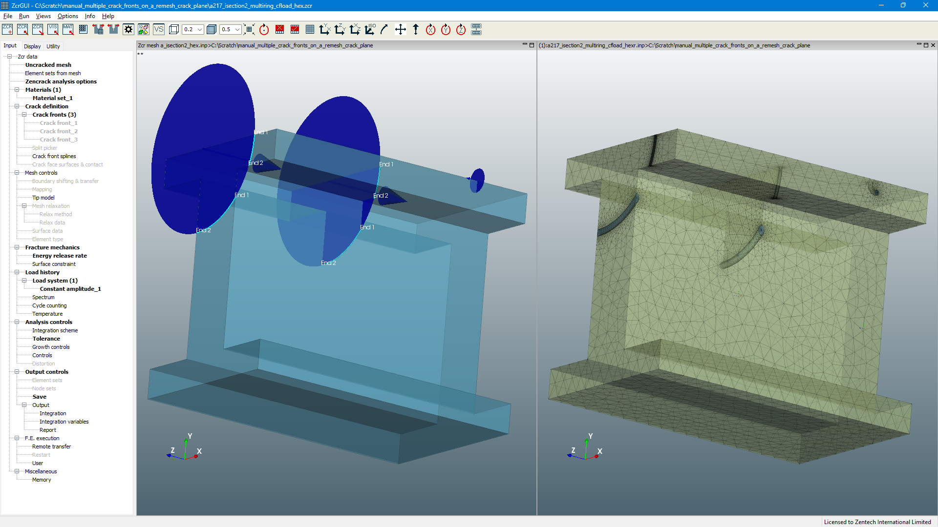
- In the remeshing method, there is a generalisation of the crack plane and crack front relationship. A geometric elliptic crack definition is now able to cut the model in multiple locations. This means that the resulting crack plane can have multiple separate crack fronts associated with it, allowing remeshing analysis of configurations that previously required use of crack-blocks. A typical example of such a configuration is a centre cracked test specimen in which one crack plane is attached to two crack fronts.
- A new material curve fitting utility is introduced for generating fatigue crack growth law parameters from sets of raw test data. Specifically, the utility allows calculation of the four parameters required for a Hartman-Schijve crack growth law. This crack growth law has been shown to be useful in combining durability results from multiple fatigue crack growth tests into a single representation that is appropriate across all tests, including: effects of varying stress ratio; application of long crack data to short cracks; application to a range of materials including metals, AM materials and composite materials. The curve fitting can be run as a command line process and is also supported via a new Utility tab in the Zencrack GUI to allow definition of the fitting process, calculation of the parameters and plotting of the raw curves and curve fits.
- The remeshing method is supported for the first time in the Simcenter Nastran interface.
Generalisation of the remeshing crack plane and crack front relationship
Remeshing now supports a more generalised relationship between crack planes and crack fronts, enabling multiple crack fronts to be connected to a crack plane. This capability is made available in the 9.5-1 release via the geometric elliptic crack definition. Such a geometric definition creates a single crack plane which may now cut more than one crack front in the model. This process is automatic, based on the interaction of the geometric ellipse and the model bounds - the multiple crack fronts are identified automatically and associated with the crack plane.
As in earlier releases, remeshing supports multiple geometric crack plane definitions and each such elliptic definition may now cut one or more crack fronts into a model.
Example 1
Example of a geometric ellipse cutting one crack plane and two crack fronts into a model to generate an initial 45 degree inclined crack

Preview of the initial crack front rings and region to be remeshed with inset showing calculated crack path (shown in Zencrack GUI)
Mises contour plot of advanced crack positions during fatigue crack growth prediction (shown in Abaqus/CAE)
Example 2
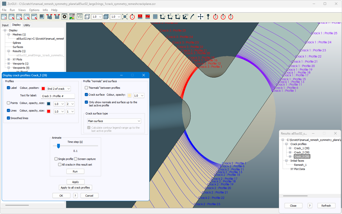
Example of a geometric ellipse cutting one crack plane and three crack fronts into a symmetry plane of a model
Preview of the initial crack front rings and crack front node positions with inset showing calculated crack paths (shown in Zencrack GUI)
Mises contour plot of advanced crack positions during fatigue crack growth prediction with mirroring about the two symmetry planes in the model (shown in Abaqus/CAE)
Example 3
Example of three geometric ellipses cutting three crack planes and five crack fronts into a model
Remeshing with the Simcenter Nastran interface
The remeshing method is supported for the first time in the Simcenter Nastran interface. All remeshing options available in the Abaqus and Ansys interfaces can be found in the Simcenter Nastran interface.
Example of post-processing in Simcenter 3D Results Viewer using a step from a Zencrack crack growth run carried out with Simcenter Nastran (whole model view)
Example of post-processing in Simcenter 3D Results Viewer using a step from a Zencrack crack growth run carried out with Simcenter Nastran (zoomed-in view)
Remeshing with improved crack plane triangulation during a growth analysis
The retriangulation option for the crack plane is changed in version 9.5-1 to be ‘on’ by default. This option is beneficial for improving the mesh distribution in the initial crack plane when both sides of the crack are modelled and, new in version 9.5-1, the retriangulation of the initial crack plane is carried through to subsequent meshes in a crack growth run - prior to version 9.5-1 the retriangulation option only affected the first cracked mesh in a growth run.
The example shows the difference in crack plane meshing that is obtained if the effect of retriangulation of the initial crack plane is carried into subsequent analysis steps. The example compares meshing at step 8 of an analysis in which the 9.4 behaviour in used and the new behaviour in version 9.5-1 in which the retriangulation is carried through all analysis steps.
Crack plane triangulation at analysis step 8 without the new retriangulation option
Crack plane triangulation at analysis step 8 with the new retriangulation option
Material curve fitting
A new material curve fitting utility is available in version 9.5-1. This allows calculation of parameters for a modified Hartman-Schijve fatigue crack growth law curve fit from one or more sets of fatigue test data.
The modified Hartman-Schijve crack growth law has been shown to be useful in combining results from multiple fatigue crack growth tests into a single representation that is appropriate across all tests, including:
- effects of varying stress ratio
- application of long crack data to short cracks
- application to a range of materials: metals, additively manufactured (AM) and cold spray AM (CSAM) materials, cold spray and adhesive repairs, delamination in composite materials, etc.
Both K and G forms of the modified Hartman-Schijve law are supported:
These equations each contain four parameters that may be modified to obtain a fit:
- D and p are coefficients similar in concept to the C and n coefficients of a Paris crack growth law and represent the central section of the Hartman-Schijve curve.
- Threshold parameter, ∆Kthr or ∆√Gthr, describes the curve behaviour in the threshold region.
- Cyclic fracture toughness, A, or failure parameter, describes the curve behaviour in the failure region.
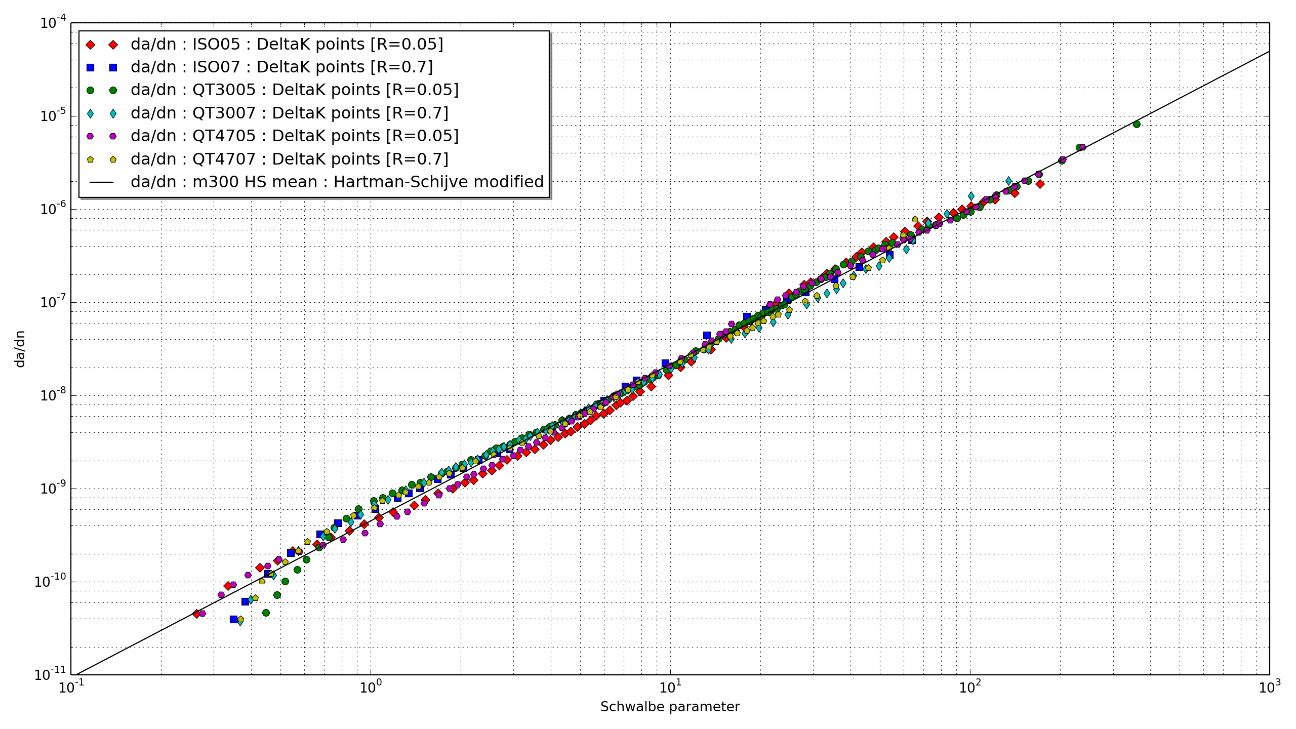
The Hartman-Schijve equation can also be written in terms of the Schwalbe parameter, ∆κ. This parameter is defined as the term which is raised to the power p.
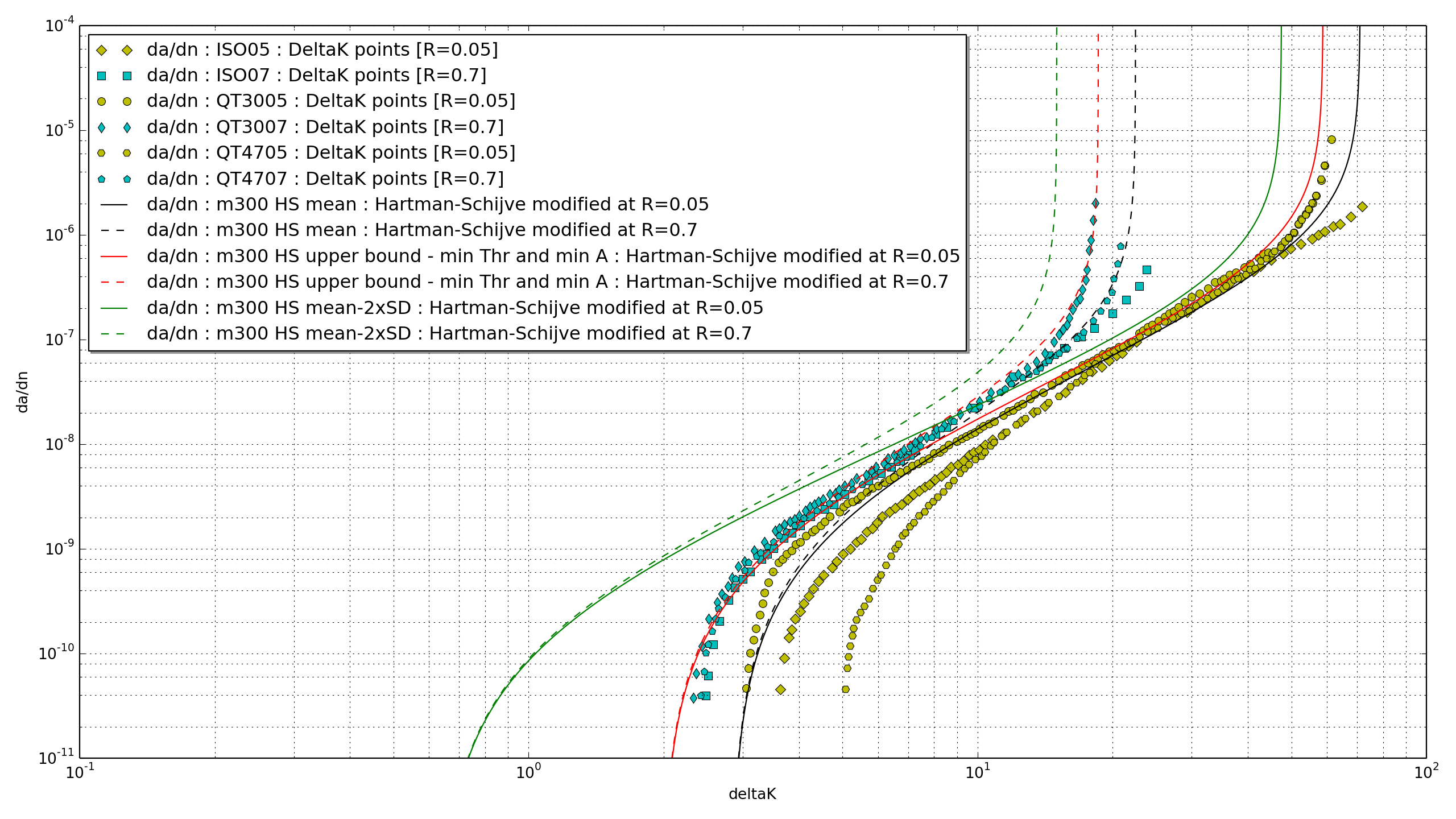
When plotted in log-log space with the Schwalbe parameter on the x-axis, the equation is a straight line with slope p and intercept D. The aim of the fitting process is to select parameters that optimise the fit of this straight line with respect to the original curve data points presented via the Schwalbe parameter. The example below shows raw and fitted data for six sets of test data plotted against ∆K and re-plotted with the Schwalbe parameter on the x-axis.
The output from the fitting process includes fit parameters for each raw data curve and parameters and standard deviation values relating to the overall "master curve fit". The output from the curve fitting process can be imported to the Zencrack GUI to enable creation of raw and fitted material plots as da/dN against appropriate x-axis parameters (e.g. ∆K, ∆√G or Schwalbe parameter).
Example of raw data points and Hartman-Schijve fits for six sets of test data, plotted against ∆K
Example of a Hartman-Schijve fit for six sets of test data, plotted against Schwalbe parameter
Zencrack GUI changes
XY plotting
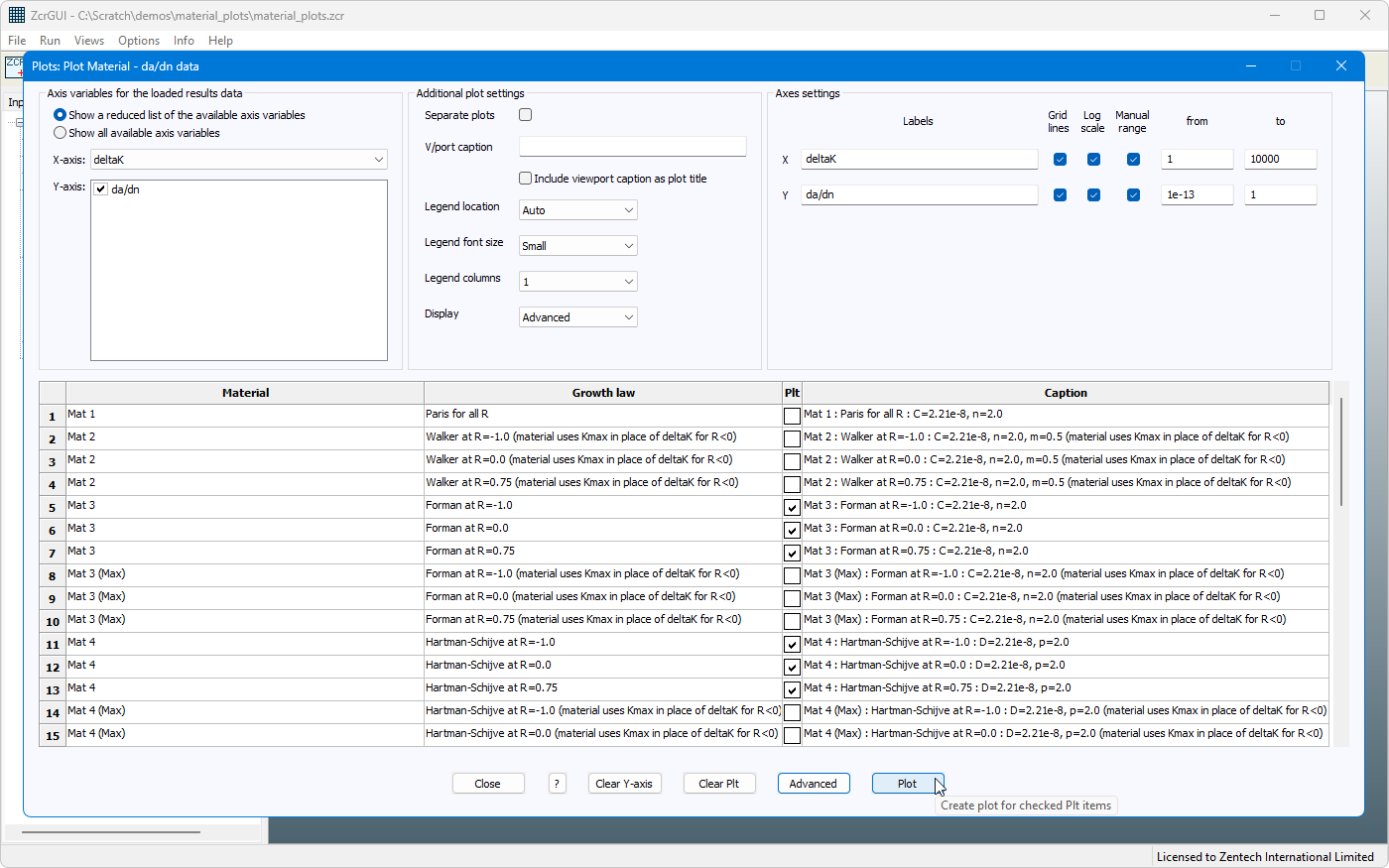
In version 9.5-1 the XY plot screens for both material and results plots are re-organised with wider tables and new options:
- Drop-down to set the legend font size.
- Drop-down to set the number of columns in the legend.
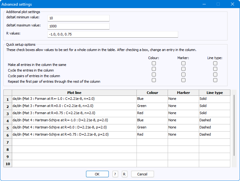
- Advanced screen entries presented in a scrollable table to cater for a high number of lines. Each colour / marker / line type entry can be clicked to convert to a drop-down box to allow changes.
- Checkboxes on the Advanced screen to allow changes of colour / marker / line type to be applied to all rows of a column.
- Increased number of marker types.
- Plot style changed to a ‘tight’ fit within the plot viewport (i.e. reduced blank space around the plot area). The ‘padded’ fit used in version 9.4-1 and earlier releases may be set via the parameter PlotFit in the zencrack_gui.ini file.
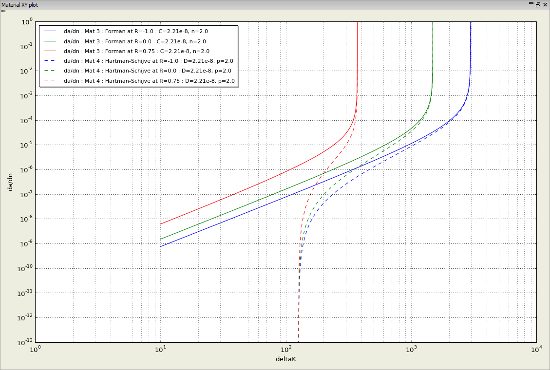
- For ‘Plot Material - da/dn data’ plots, sqrt(Gmax) is added to the available plot variables when a G-based law is plotted.
- For ‘Plot Material - da/dn data’ plots, the following material types are added to those that may be plotted:
- Delta K points
- Delta G points
- Delta sqrt(G) points
Display of crack profiles
The display attributes of crack profile labels can be controlled with new options to set colour, position and label text.
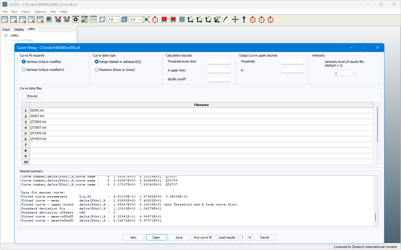
Utility tab and material curve fitting
A new Utility tab is included to allow access to Zencrack utility programs. In the 9.5-1 release only the new material curve fitting option is enabled on the Utility tab.
The new material curve fitting screen allows:
- Creation and review of input data for the material curve fitting program.
- Execution of curve fitting.
- Loading of curve fitting results to allow plotting of material curves.
Miscellaneous GUI changes
The character encoding changes made in version 9.4-1 of the GUI are further extended to provide additional information in error messages when there is an encoding issue while opening a file.
An extra check is added to prevent an attempt to execute a ‘Run Zencrack’ option from the GUI if the specified file is defined with a UNC file path
During remeshing, the use of an element set to restrict the remeshing region is updated to ensure that any intersections of the geometric crack definition with the model bounds that occur outside the element set are ignored.
Other Changes
General
A new standard crack growth law type is added, *CRACK GROWTH DATA, TYPE=Delta sqrt(G) points. This allows input of a single growth law as points of (delta sqrt(G), da/dN).
Parameter MAX is added and existing parameter R is extended on the *CRACK GROWTH DATA keyword:
- The new MAX parameter is allowed with TYPE=Delta K points and Delta sqrt(G) points. It indicates the constant Kmax or sqrt(Gmax) value of the curve data. It is enabled for information only and does not affect the analysis results. The value is made available when plotting material data in the GUI.
- The R parameter is allowed with TYPE=Delta K points and Delta sqrt(G) points in addition to the previously allowed TYPE=Delta G points. It indicates the constant stress ratio value of the curve data. For the new additions, it is enabled for information only and does not affect the analysis results. The value is made available when plotting material data in the GUI.
Configuration file zencrack.gui
From version 9.5-1, the zencrack.ini file includes a new section [VERIFIED] which defines versions of the interfaced f.e. codes that have been verified at the time of release of the Zencrack version. If a future f.e. code version is ever used, compatibility cannot be guaranteed and a warning is issued to the .rep file.
The setup program is modified to enable configuration of zencrack.ini with the Intel Fortran ifx compiler (depending upon the installed Fortran version).
Configuration file zencrack_gui.ini
New entry PlotFit specifies the style of XY plot layout.
New entry RemeshSymmetryPlaneFully allows enabling full remeshing of the crack plane on a symmetry plane.
Modified entries PlotLegends, PlotLegendsAdvanced, PlotLegendsAdvancedMaterial include new marker types.
Documentation
A new sub-section ‘Crack growth direction’ is added to the ‘Loading’ section of the User Manual to consolidate information about the way that crack growth direction is handled for different types of load systems and spectra.
Abaqus interface
The keyabq.dat file is updated for Abaqus 2025.
The status value of Abaqus keyword *DIAGNOSTICS is changed to zero to allow it to be used.
Ansys interface
The keyans.dat file is updated for Ansys 2025R1.
Changes are made to support the new DBLOCK option introduced in Ansys 2025R1. This new option can cause some Zencrack jobs to fail if using Zencrack 9.4-1 (and earlier) with Ansys 2025R1.
Tied surface behaviour in Zencrack models using Ansys 2024R2 onwards may be different than when using earlier Ansys versions due to changes in the way that default KEYOPT values work for target and contact elements. Changes are made to ensure consistent behaviour across Ansys versions up to 2025R1.
From Ansys 2024R2, any SURF154 elements in the contour integral region generate a fatal error rather than a warning (even if there is no load applied to those elements). Changes are made to the update process of surfaces in the crack region to ensure that element based loads (SFE) are applied in the contour integral region rather than surface based (SURF154) loads.
The allowed number of Ansys material ids, real types and tshap lines are each increased to 9999. The previous limits were 200 and 1000 material ids in Zencrack and the Ansys converter, and 999 real types and tshap lines.
The check for parameters cid and tid on Ansys *SET options and subsequent updates when these parameters are used, is extended to also check for _tid and _cid.
The handling of E options defined with parameter values within if..endif loops is improved to ensure that such definitions are retained in the cracked mesh.
Shell section types are now processed on EBLOCK options.
The *GROWTH CONTROLS, DIRECTION=Preferred option is allowed in the Ansys interface.
Simcenter Nastran interface
The remeshing method is fully supported in the Simcenter Nastran interface using the *CRACK FRONT keyword for remeshing.
Local coordinate systems are now processed (grid CP and CD options):
- In the 9.5-1 release, Zencrack processes the Nastran CP and CD fields on GRID keywords:
- The Simcenter Nastran basic Cartesian coordinate system is the default coordinate system in a Nastran analysis. The Simcenter Nastran global coordinate system is a collection of transformed coordinate systems defined via the CD fields of the grid points of each element. In addition to the CD grid data field, the CP grid data field can be used to allow the three coordinate values of a grid point to be defined in a local cartesian, cylindrical or spherical system. All coordinate system transformations, whether for the grid CP or CD fields, are defined via the CORD1C, CORD1R, CORD1S, CORD2C, CORD2R and CORD2S options.
- The Zencrack ‘global coordinate system’ is equivalent to the Simcenter Nastran basic coordinate system.
- Local coordinate systems for CP coordinate definitions are supported by Zencrack when processing GRID keywords. The CP entry on the grid data line is used to convert the local coordinates of the grid point to equivalent Nastran basic (x,y,z) Cartesian coordinates. All nodal coordinate data for the cracked mesh is written with a zero value for CP (i.e. in the Nastran basic coordinate system, which is the same as the Zencrack global coordinate system).
- Local coordinate systems for CD transformations are read from the uncracked mesh and applied onto new nodes added into the cracked mesh using a number of rules to ensure sensible updates are carried out (see Simcenter Nastran Interface Manual).
- When extracting displacement data from the .op2 file, Zencrack expects the displacements to be in the basic coordinate system. If necessary, a PARAM, OUGCORD, BASIC option is automatically added to the cracked mesh to achieve this.
The *GROWTH CONTROLS, DIRECTION=Preferred option is allowed in the Simcenter Nastran interface.