- Software
- Zencrack
- Technical
- Load Definition
Complex Load Histories
Load Definition
Complex Load Histories
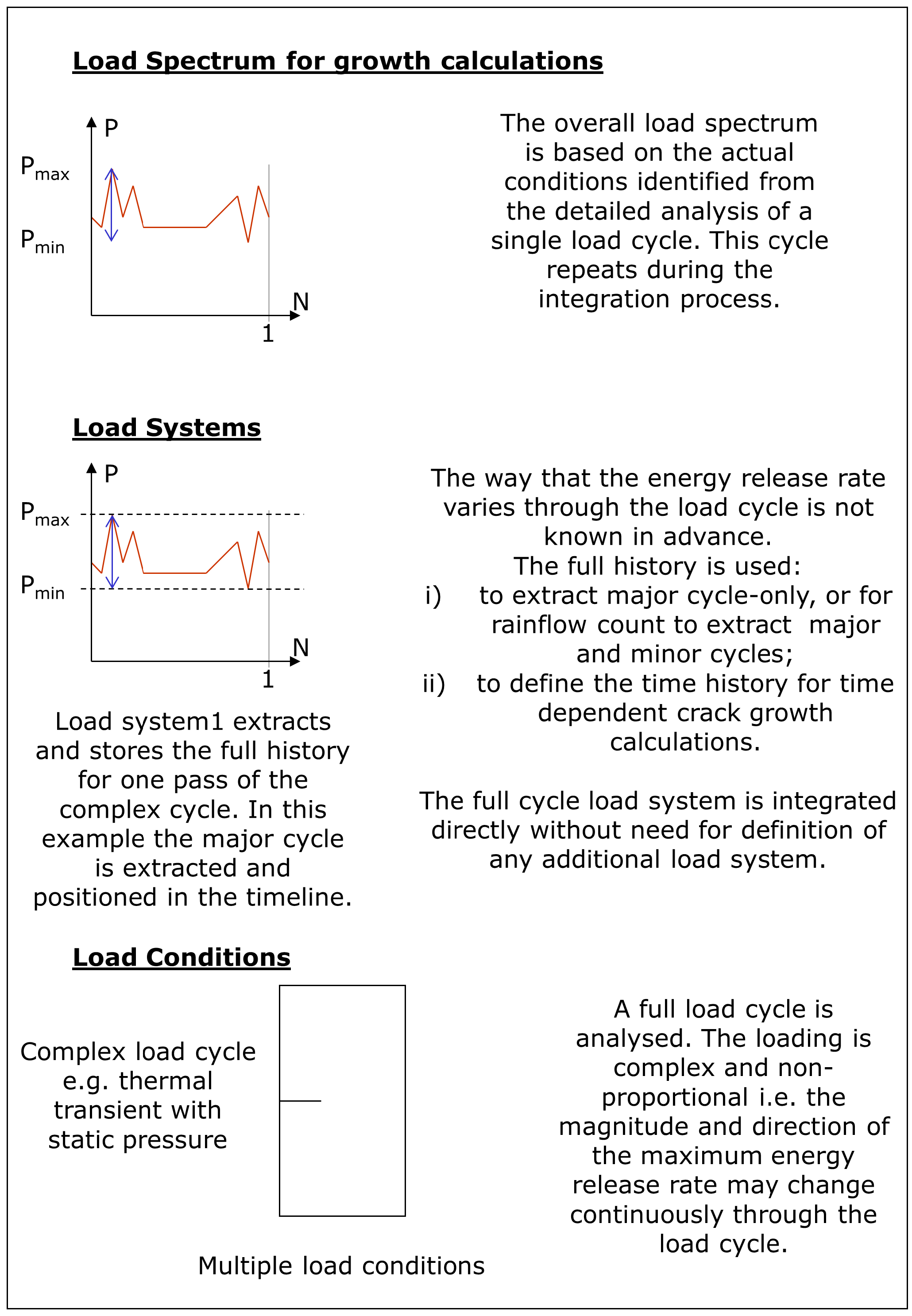
A "full cycle" load system can be defined for crack growth due to complex load cycles. This type of load system allows detailed analysis of a completely general load cycle within the f.e. analysis. Such a cycle may include out-of phase stress and temperature variations and non-linear effects such as contact. A typical application of the "full cycle" approach would be for crack growth analysis in an aircraft engine component in which a complex load and thermal history exists through the take-off, climb, cruise and landing phases of a flight cycle.
Energy release rates and stress intensity factors are calculated at each crack front node throughout the complete load cycle and are used to drive the crack growth integration. This integration may be time-only, fatigue-only or include both time and fatigue crack growth effects. This "full cycle" capability is of particular importance in high temperature applications where the influence of time dependent crack growth can be significant.
The "full cycle" capability includes:
- Fatigue-only, time-only or combined fatigue-time crack growth analysis.
- Full thermo-mechanical crack growth analysis with out-of-phase stress and temperature histories.
- Optional application of a shakedown adjustment factor to account for reduction in peak stress due to elastic shakedown.
- Fatigue options for inclusion of :
- major cycle only
- major cycle plus exchange rate
- major and minor cycles
For the fatigue options, the exchange rate method accounts for minor cycle effects without explicit inclusion of the minor cycles. For the major and minor cycle option, a rainflow count is performed on the extracted K history for each crack front node. The counted cycles are positioned within the timeline and their effect is added into the crack growth as the timeline is integrated.

Schematic for time history variation of K at a crack front node
For a general complex cycle there may be different temperatures associated with the maximum and minimum conditions for each fatigue cycle. Therefore, several options are available to define the method for temperature handling when calculating da/dn for a cycle. In the schematic example shown here where the major cycle is defined by the range Sq to Sp:
- use the temperature at the Kmax condition for the particular fatigue cycle (whether it is a major or minor cycle) (Tp in the example)
- use the maximum temperature in the entire load cycle (Tmax in the example)
- use the mean da/dn from the above two methods
- use the average temperature at the Kmax and Kmin conditions (average of Tp and Tq in the example)
A "combination" load system is also available. This allows combination of multiple load spectra applied as discrete loads each having a time variation. The resulting combination can optionally be cycle counted during the crack growth integration process. A set of static and cyclic load systems and can also be combined. This approach is only appropriate if the individual systems can be combined by superposition. When non-linearities occur, an alternative to the full cycle approach is the minimum-maximum method in which minimum and maximum conditions during the load cycle must be analysed explicitly as two steps in the f.e. analysis to define the range for crack growth calculations.
Technical
Load Definition
More in this category