- Software
- Zencrack
- Technical
- Meshing Procedure
Crack-block Method
Meshing Procedure
Crack-block Method
The crack-block meshing procedure is one of replacement of one or more 8 or 20 noded brick elements in a user supplied uncracked mesh by crack-blocks. Crack-blocks contains sections of crack front and are used to build the required initial crack(s).
The Crack-block Methodology
The elements forming the crack front in each crack-block are modelled using collapsed 8 or 20 noded brick elements with the element type based on the user's uncracked mesh. For 20 noded elements, the user has an option to control the midside node positions extending radially from the crack front - the default option provides quarter point nodes. The crack front itself is seen as a line of nodes on the crack-block surface. The internal mesh of the crack-block coarsens away from the crack front such that some of the crack-block faces can be matched with standard brick elements to allow them to be merged with a user-supplied mesh. These crack-blocks are referred to as standard crack-blocks. The other highly populated faces can be left as free surfaces, symmetry surfaces, or connected to other compatible crack-blocks. In some crack-blocks all of the external surfaces are highly populated surfaces. These special crack-blocks, referred to as large crack-blocks, must be tied to the rest of the user-supplied mesh.
In the simplest case of all, a cracked mesh may contain only a single crack-block (and therefore a single crack front). If there is a single crack-block then only one side of the crack (i.e. one crack face) is modelled and symmetry constraints should be applied. These can be applied in the uncracked mesh and automatically updated by Zencrack.
If both sides of the crack (i.e. both crack faces) are to be modelled, then pairs of crack-blocks are used with a face-to-face match of the crack-blocks. An example with crack-blocks used in a face-to-face match is shown below. This is a displaced plot with the visible part of one crack face shaded for clarity.

Example with both sides of the crack modeled. This example uses large crack-blocks that are tied to the surrounding mesh.
Crack-blocks are grouped into "families" for ease of use. All crack-blocks within a family can be placed alongside one another to form a crack front. The different crack-blocks within a family may have different numbers of elements along their individual crack fronts giving flexibility in their application. A typical crack-block family is shown below.
Initial Crack Definition
The initial crack is defined by replacing one or more elements by "crack-blocks" to build up one or more crack fronts in the model. Each crack-block models a section of crack front and the combination of multiple crack-blocks allows modelling of a complete crack. The replaced elements are identified by their element numbers and the orientation of the crack front section in each is defined by two node positions on each replaced element.
The initial crack size can be specified in three ways:
- using ratios along two edges in each replaced element
- using absolute sizes along two edges in each replaced element
- using a spline that defines a complete crack front
The first two methods are appropriate for simple meshes in which the elements are fairly regular. The user only has control over key points along the crack front section with intermediate points determined by the element shape functions.
The spline method is extremely powerful and gives total control over the entire crack front shape. Crack front nodes are placed onto the spline and the crack-blocks are mapped into the element space taking account of the crack definition.
The Zencrack input file contains a number of keywords to define the required input data. The initial crack front is specified using one *CRACK FRONT keyword for each distinct crack front in the model. For the example of an elliptic corner crack shown here the spline method is used. The input is:
*CRACK FRONT, INITIAL=POINTS, SPLINE=STARTER
s01_q103x4 826 1203 1204
s01_t88x5  824 1203 1255
*SPLINE, NAME=STARTER
0  2.451963E+00  9.902455E+00
0  2.500000E+00  1.000000E+01
0  2.451963E+00  1.009755E+01
0  2.309699E+00  1.019134E+01
0  2.078674E+00  1.027779E+01
0  1.767767E+00  1.035355E+01
0  1.388926E+00  1.041573E+01
0  9.567086E-01  1.046194E+01
0  4.877258E-01  1.049039E+01
0  0.000000E+00  1.050000E+01
0 -4.877258E-01  1.049039E+01
This input specifies that element 826 is replaced by crack-block s01_q103x4 with crack orientation using nodes 1203 and 1204. Element 824 is replaced by crack-block s01_t88x5 with crack orientation via nodes 1203 and 1255. The initial crack shape is cross-referenced to a spline named STARTER.
This screenshot shows an example of the process for defining an initial crack front in the Zencrack GUI. This is the simplest way to define the crack front as it allows creation of the keyword input data without the need to manually extract element and node numbers for the crack-blocks. Instead, the target elements and nodes are picked from the uncracked mesh.
Deep cracks
For deep initial defects the Zencrack deep crack option can be used to separate pairs of standard elements that are on the crack faces. To use this option the user replaces some elements by crack-blocks and also defines element split pairs. Each element split pair contains two elements that straddle the crack face. Zencrack separates these elements.
Example of a deep crack modelled at 30% wall thickness with one layer of standard elements separated. This example also uses boundary shifting (see below).
Boundary Conditions and Loading
All merging of crack-blocks with one another and with the uncracked mesh is carried out automatically to create the new finite element mesh containing the required crack fronts. During this mesh creation, Zencrack updates information related to the crack-block region e.g.:
- Pressure loads on the outside of the crack-blocks
- Body loads such as centrifugal loading
- Applied boundary conditions
- Temperature distributions
The initial cracked mesh can be analysed as a one-off crack size or as the first step in a crack growth analysis.
Boundary Shifting And Mesh Relaxation
When standard crack-blocks are used there are additional options available to control the overall size of the replaced elements. This is to help minimise distortion within the crack-blocks. This also allows analysis of a wide range of crack sizes from the same uncracked mesh.
The options available include boundary shifting and mesh relaxation. These options allow cracks to be placed in meshes where element distortion would otherwise preclude the analysis of the mesh. The boundary shift algorithm adjusts the external boundaries of the crack-blocks such that the element distortion inside the crack-block is reduced. The mesh relaxation algorithm then attempts to re-distribute the nodes outside the crack-blocks to reduce any distortion introduced by the boundary shifting.
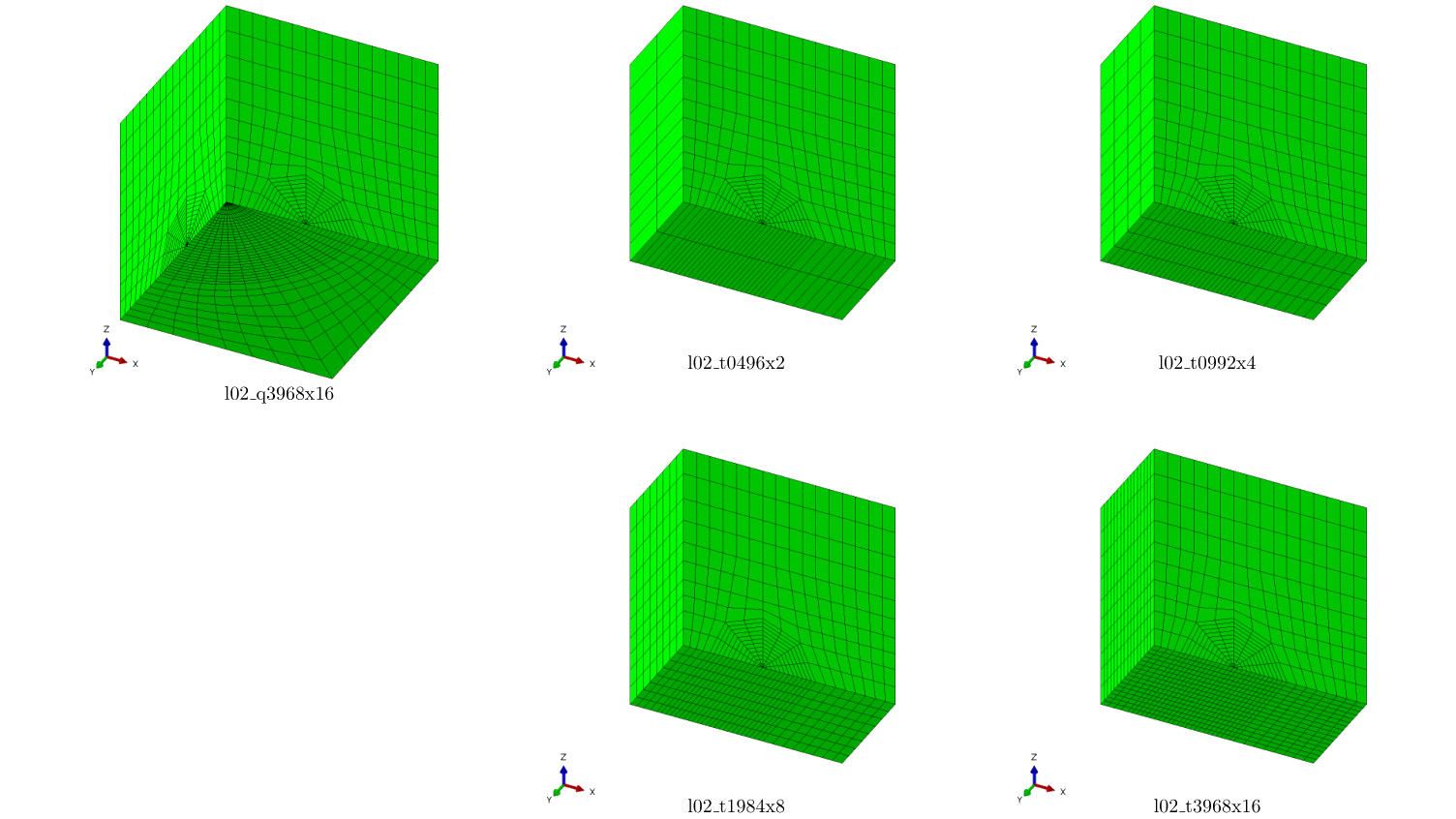
A simple example is given here for an elliptic crack made up of a line of standard through crack-blocks. These features are extremely useful in parametric studies of different crack sizes in the same uncracked mesh and during crack growth analyses when using standard crack-blocks.
Example of the effect of boundary shifting in the region outside the crack-blocks
Technical
Meshing Procedure
More in this category