- Software
- Zencrack
- Technical
- Meshing Procedure
Remeshing Method
Meshing Procedure
Remeshing Method
The Zencrack remeshing capability provides mesh independent crack insertion into an uncracked mesh. This approach simplifies the creation of 3D models containing cracks by using a purely geometric definition of an initial crack.
An existing uncracked mesh can be used "as-is" with, in most cases, no need to perform special partitioning or meshing of the uncracked geometry. This means that, for example, a single uncracked mesh can be used to develop models of significantly different cracks by simply changing the geometric crack definition.
Initial crack and crack growth
- remeshing for analysis of initial crack only
- remeshing for general non-planar 3D crack growth using the load system methodologies in Zencrack for fatigue, time dependent and combined fatigue/time crack growth prediction
Geometric definition of an initial crack
- initial crack location is fully independent of the underlying mesh
- the underlying mesh may contain hex or tet elements
- crack at a symmetry plane, surface breaking or fully embedded
- initial crack shape may be straight or elliptic (either full ellipse or elliptic arc)
Remeshed region split into hex rings and surrounding tets
- rings of hex elements at the crack front with ring mesh density controlled by the user
- tet mesh surrounding the rings
- fully automatic calculation of the extent of the remeshed tet region and mesh density within that region (with manual control if desired)
Support for static, thermal and coupled analyses
- update of displacement boundary conditions, pressure loads, surface definitions, film coefficients and temperatures in the remesh region
- optional application of pressure and/or film coefficients to the crack face
Full support in the Zencrack GUI
- option to define geometric positional data by picking nodes in the uncracked mesh
- preview of the geometric crack definition
- preview of the hex rings at the crack front
- preview of the remesh region
- preview of the remesh region with the crack inserted
Interface support
- remeshing is available in the all finite element interfaces
- Abaqus : from version 9.0-1
- Ansys : from version 9.1-1
- Simcenter Nastran : from version 9.5-1
An Example of Initial Crack Definition
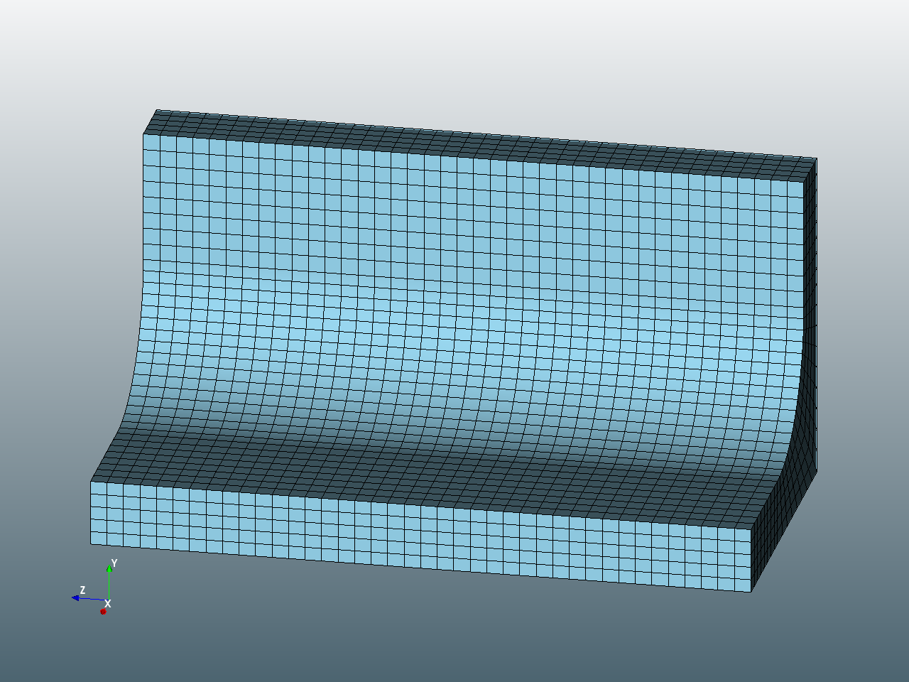
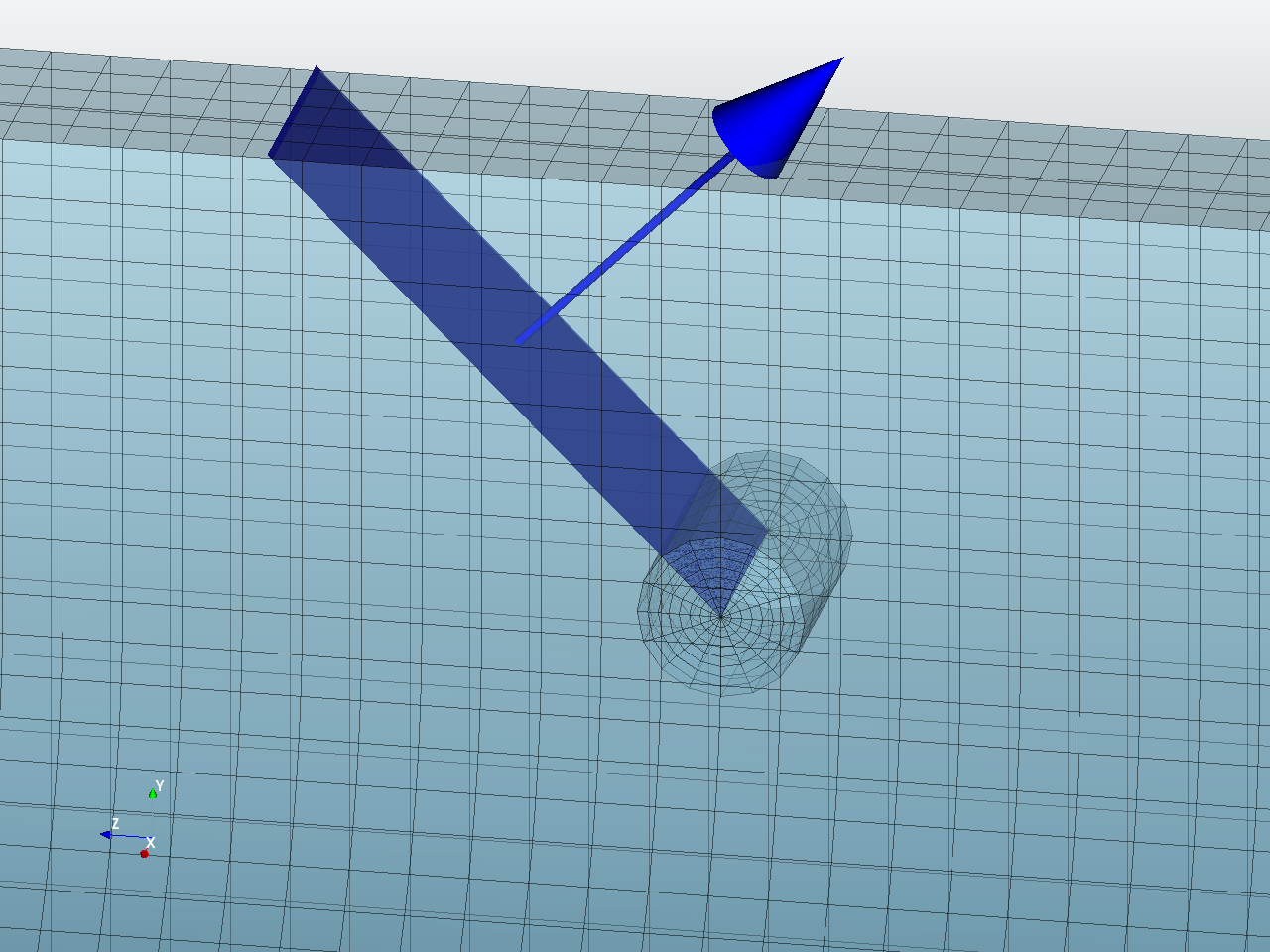
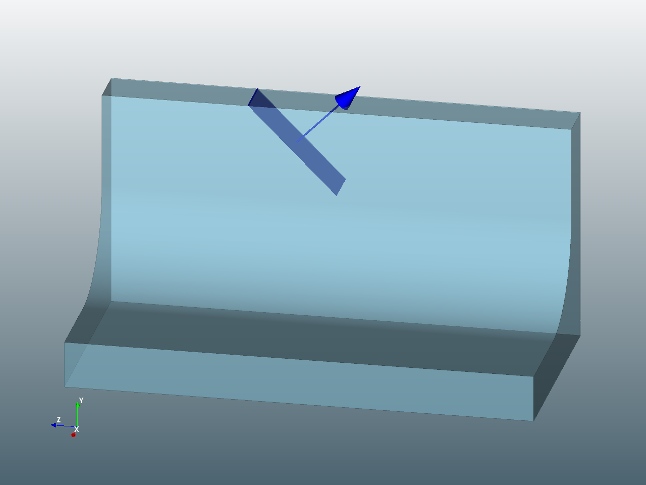
An overview of the remeshing process is given here using an example of a slanting crack introduced into an underlying hex mesh. The required crack in this example is a straight crack front with an inclined crack plane. Once the geometric data has been input to the Zencrack GUI, a preview of the geometric crack plane (blue surface with an arrow normal to the surface) can be generated.
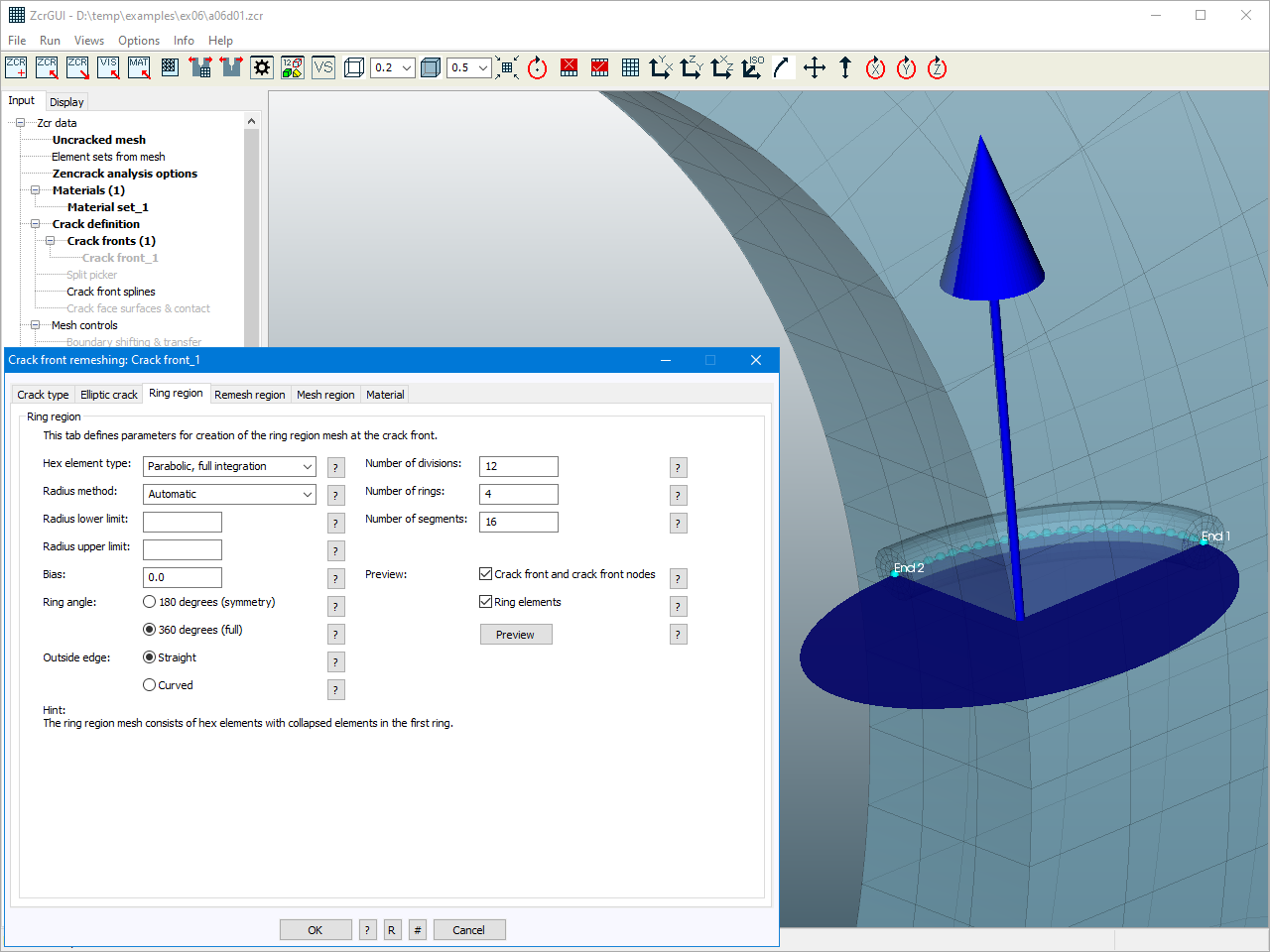
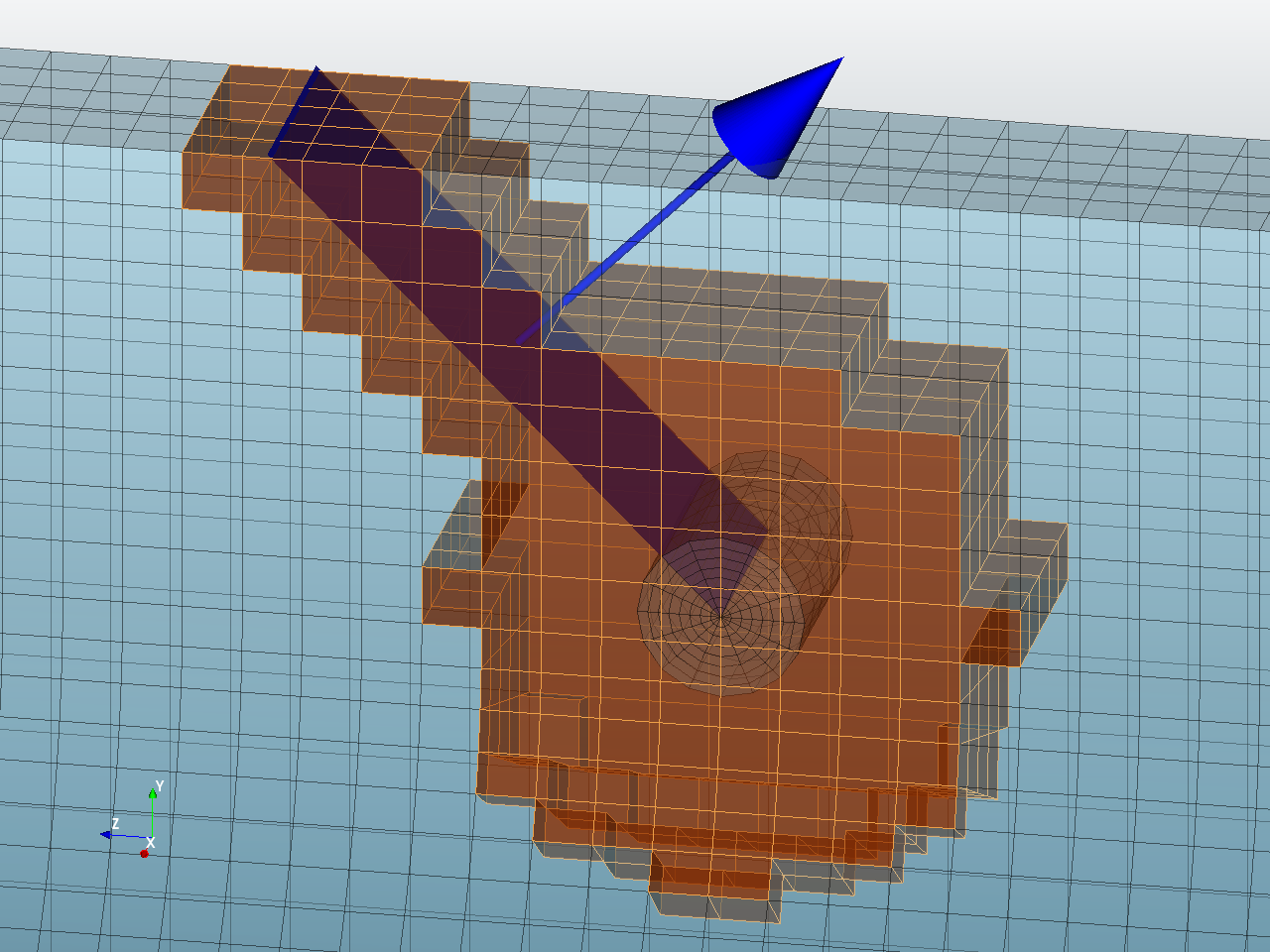
The hex ring region at the crack front is defined by a minimum set of data consisting of:
- the number of elements along the crack front
- the number of rings (i.e. the number of elements in the radial direction)
- the number of segments (i.e. the number of elements in the theta direction - around the 180 or 360 degrees of the rings)
From the definition of these rings parameters the ring radius and the extent of the remesh region can be calculated automatically. This is the recommended approach. However, options are available to directly specify the ring radius and the remesh region if required. The Zencrack GUI can provide a preview of the rings and the extent of the remesh region for the initial crack.
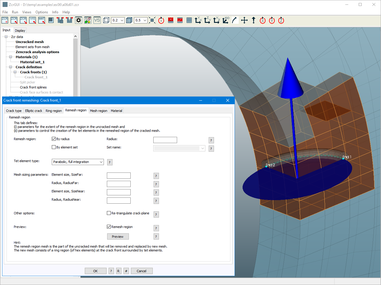
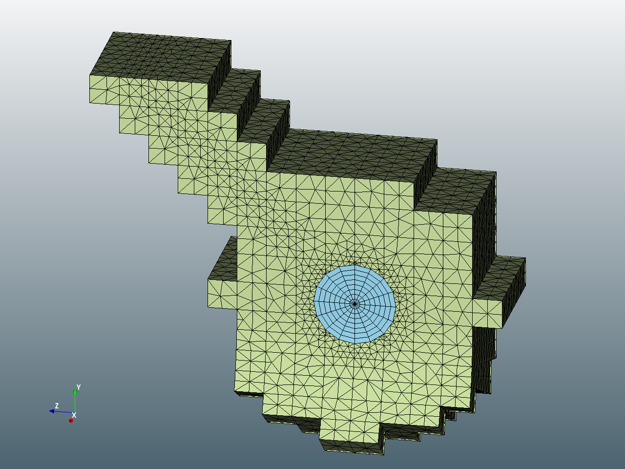
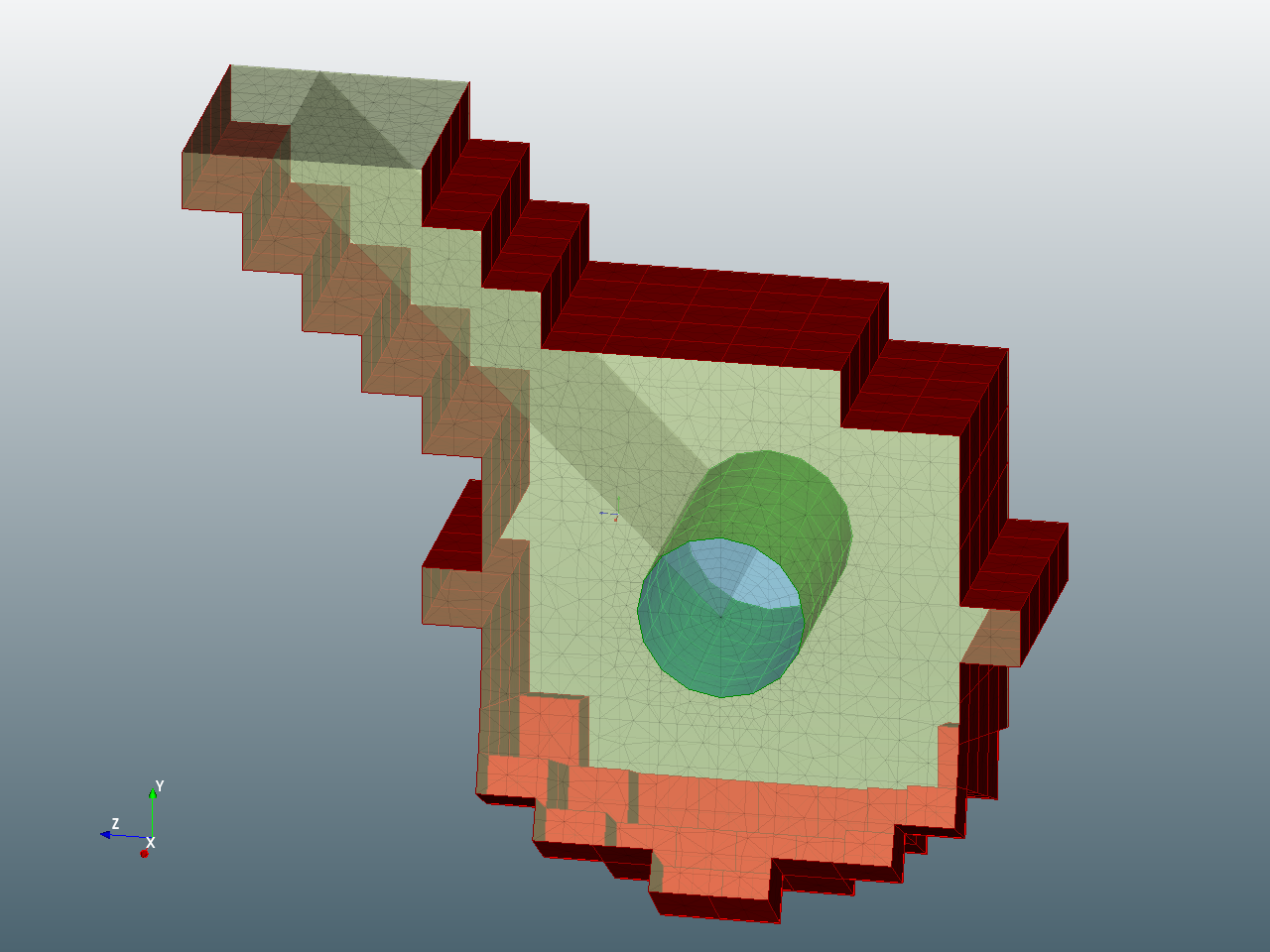
The mesh size for the tet mesh is also calculated automatically based on the ring details and the element sizes in the unmodified region surrounding the tet elements. Alternatively, options are available to control the mesh size in the tet region if required. However, care should be taken if setting manual meshing controls for the tet region. Trying to create too coarse a mesh can cause the process to fail. Making the mesh too refined can very easily lead to a much larger model size than may be necessary.
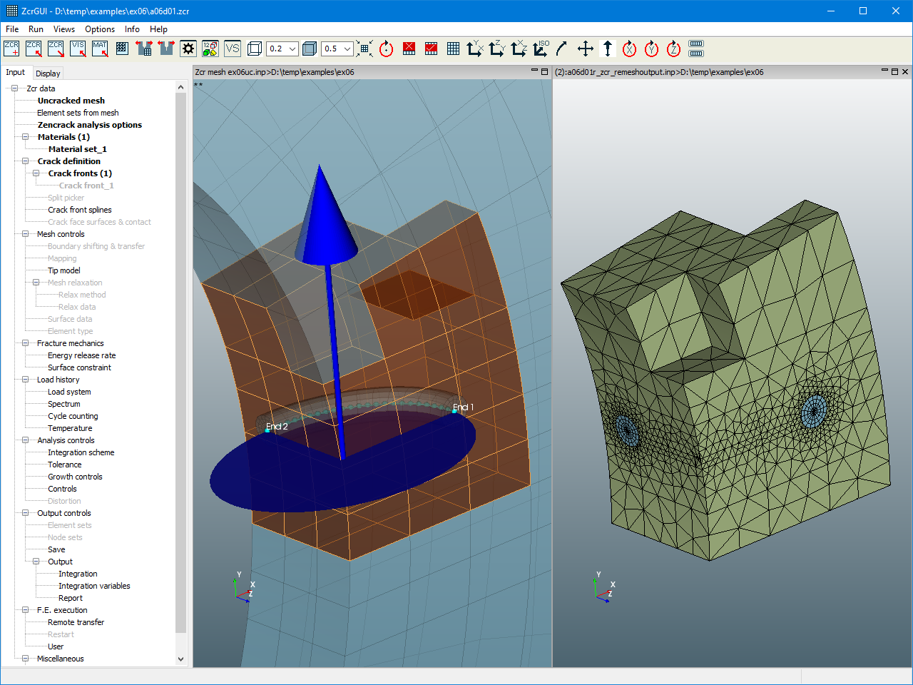
Once the ring and tet meshes are generated an appropriate set of tying surfaces are created to tie the rings to the tet region and the tet region to the surrounding mesh.
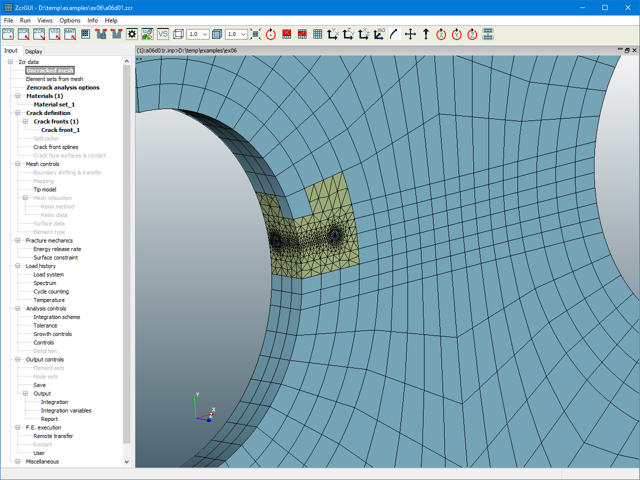
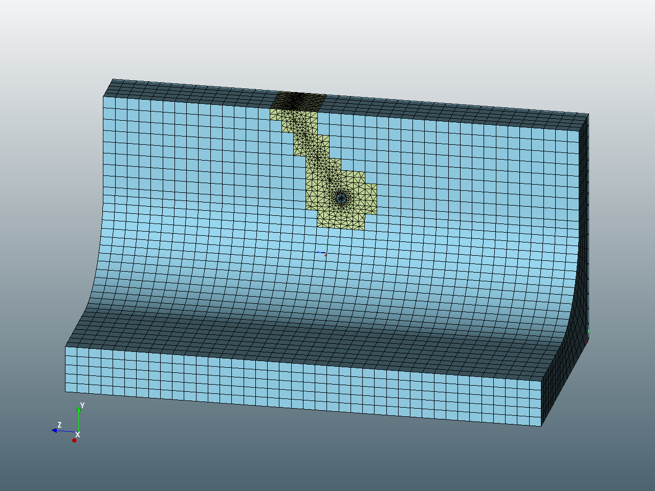
The final mesh is shown with the keyword input data used for the crack definition. By changing some of this simple input data, a different cracked mesh can readily be created. The final image shows a mesh with a changed crack plane obtained by modifying one of the coordinate points in the geometric definition. The number of rings has been reduced to 4 and the ring radius is reduced to 0.2.
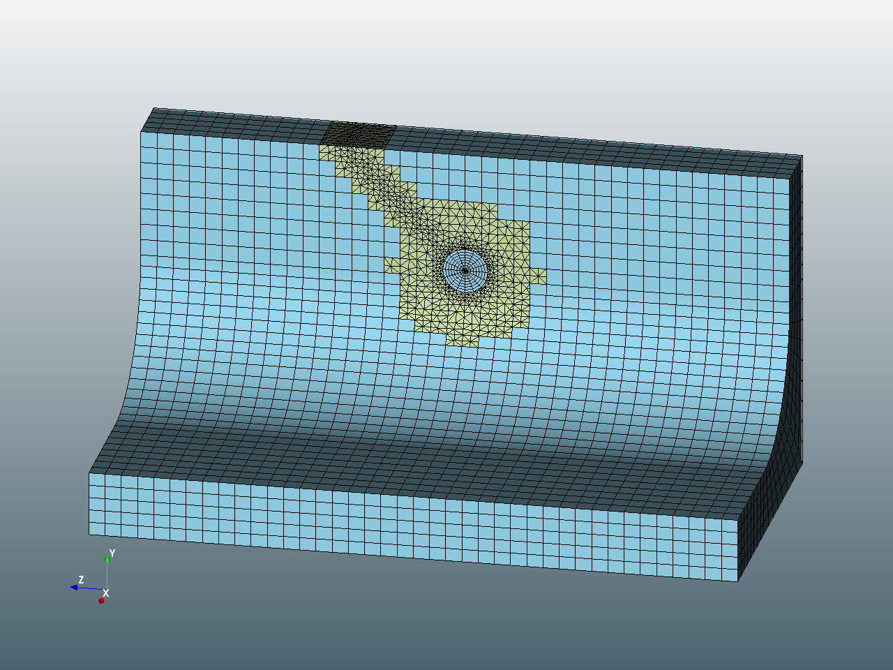
*CRACK FRONT,TYPE=Remesh,CRACK TYPE=Straight
5, 8, 16, 0.7, 0.7, 360
 , , ,
2, 6.25, 10
0, 6.25, 10
2, 10, 13.75
 , ,
5 elements along crack front, 8 rings, 16 segments around 360 degrees with ring radius 0.7.
Three points define the crack plane.
Remesh region calculated automatically.
Tet mesh density calculated automatically.
*CRACK FRONT,TYPE=Remesh,CRACK TYPE=Straight
5, 4, 16, 0.2, 0.2, 360
 , , ,
2, 6.25, 10
0, 6.25, 10
2, 10, 12.16506
 , ,
5 elements along crack front, 4 rings, 16 segments around 360 degrees with ring radius 0.2.
Three points define the crack plane.
Remesh region calculated automatically.
Tet mesh density calculated automatically.
Four examples are shown here of crack growth prediction with a single crack. Each simulation is carried out in a single automated Zencrack analysis.
Inclined straight starter crack in a 4-point bend specimen with a hole. The final animation shows a straight through (not inclined) starter crack located closer to the hole. This deviates towards the hole rather than growing past it.

Technical
Meshing Procedure
More in this category