
- Software
- Zencrack
- What’s New in Zencrack?
Zencrack 8.0-1
What's New in Zencrack?
Zencrack 8.0-1
Zencrack version 8.0-1 was finalised on 3 February 2016
This release includes:
- Dedicated screens for all input data in the GUI, replacing text input for some keywords.
- Improvements to crack-block and split set picking in the GUI.
- Ability to define multiple materials in the input file.
Zencrack GUI
Six new icons have been added to the toolbar for faster access to file operations and for submitting Zencrack analyses.
A new Info drop-down menu is added to allow access to error and warning messages, the current input data in keyword format and the GUI logfile.
The method of "text input" for certain keywords used in previous GUI versions is removed and all input is now carried out on dedicated input screens. These are categorised into several sections on the Input tab with, in most cases, each entry within each section corresponding to one keyword in the input file:
- Materials
- Crack definition
- Mesh controls
- Fracture mechanics
- Load history
- Analysis controls
- Output controls
- F.E. execution
- Miscellaneous
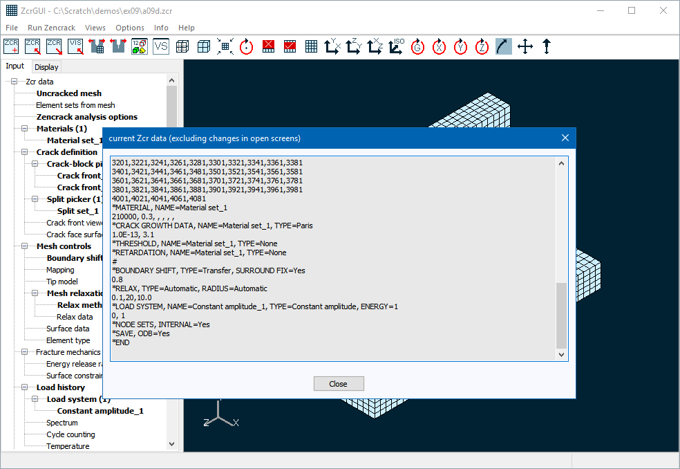
The current input data can be viewed in keyword format at any time via the 'Info -> List current Zcr data' option. The default behaviour is that only non-default keyword options are saved to the .zcr file. This can be modified such that all keyword data values are saved to the .zcr file by changing the 'Save default values' setting on the General tab of the 'Options -> Settings' screen.
A new capability is introduced on the input data screens to allow data for that screen to be reset to default values by clicking the 'reset defaults' button on the screen.
Error and warning checks are included to verify data on an input screen before the data is committed.
Error and warning checks are included to confirm that no cross-referencing issues arise due to incompatible data on two or more screens.
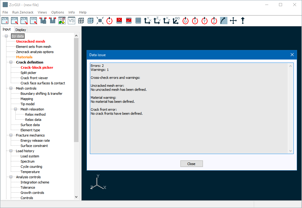
The Input tab is colour coded to indicate the status of each entry:
- Black (normal) - All data for the item is default data.
- Black (bold) - Non-default data exists for the item.
- Orange - A warning has been set for the item.
- Red - An error has been set for the item.
- Blue - Some action was taken to resolve an issue for the item when a .zcr file was opened.
For items with warnings or errors, the item can be clicked and the F1 key pressed to open a screen showing the issues for that item. A full list of warnings and errors can be seen via the 'Info > List errors and warnings' option (as in the above example). The blue colour coding only occurs after a .zcr file has been read and persists until some data is modified. A list of items related to these special blue highlights can be found in the logfile via the 'Info > List logfile' option.
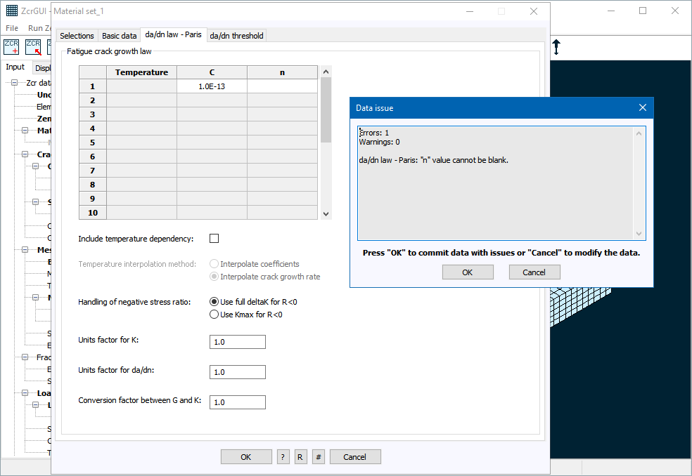
Support for the new multiple material capability in Zencrack is provided via the Materials entry on the Input tab. Each material definition includes basic material data and whatever is required in terms of crack growth data, threshold and retardation data. In this respect the material entries are slightly different than other data screens because each material definition creates several keywords in the .zcr file.
When defining a crack front a cross-reference is given to a material definition on the 'crack-block' tab of the crack-block picker screen. This material definition is then applied along the entire crack front.
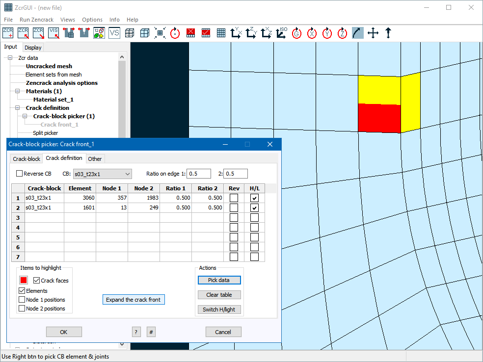
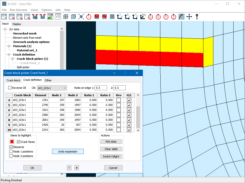
A number of enhancements are made in the 'crack definition' tab of the crack-block picker screen to speed up the process of defining a crack front:
- A new set of options above the table allows data for the next crack-block to be set without having to switch to and from the crack-block tab.
- A new column in the table allows crack-blocks to be set into reversed mode (where the crack face and ligament parts of the crack-block are reversed).
- An 'Expand the crack front' option is available to expand the crack front once the first crack-block is defined. This capability existed in Zencrack 7.9 but is new in the GUI and gives instant feedback of the complete crack front definition.
- The crack-block picking procedure is improved such that if an element is picked adjacent to an element that has previously been picked it is not necessary to pick two nodes to define the crack orientation - it is calculated automatically from details for the adjacent element and the currently selected crack-block.
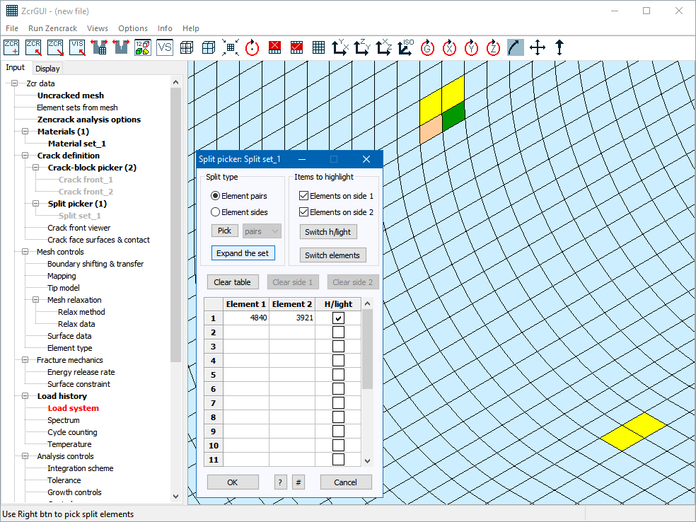
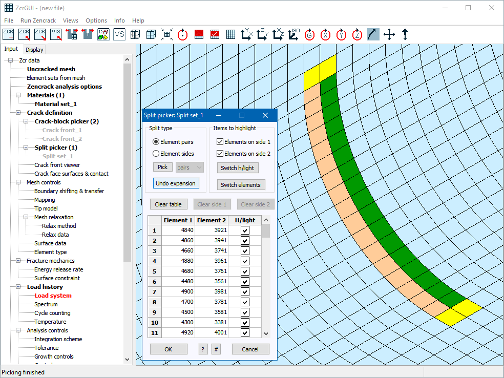
An 'Expand the set' option is also added to the split set picker screen. As with the crack front expansion this capability existed in Zencrack 7.9 but is new in the GUI and gives instant confirmation of the complete split set definition.
When using the GUI to define load systems some additional checks are included to assist with creation of additional load systems. For example, if a minimum load system is defined it is likely that maximum and max-min combination load systems will be required. A prompt is provided for automatic creation of these additional load systems.
A new option is added to the .ini file to control the GUI start-up size or whether to start maximised.
Some of the colour options (e.g. mesh viewport background and foreground) can now be set in the 'Options > Settings' screen to allow changes to be applied during a GUI session.
Finally, some improvements are made to cater for cases where Windows font scaling is set to non-standard values and to address some minor issues that affected Windows 10.
Zencrack changes
A new capability is introduced to allow multiple materials in the Zencrack input file. The implementation allows definition of multiple materials with each crack front being cross-referenced to one material. The material definition is then applied to all nodes of the crack front.
A material definition may consist of basic data (e.g. Young's modulus, Poisson ratio), crack growth data (fatigue and/or time), threshold data (fatigue and/or time) and retardation data. If any of these are not relevant they may simply be omitted or defined with parameter TYPE=None.
The definition of multiple materials requires a NAME parameter on the following keywords:
*MATERIAL, *CRACK GROWTH DATA, *THRESHOLD, *RETARDATION
A cross-referencing MATERIAL parameter is used on the *CRACK FRONT keyword.
Multiple material definitions are constructed based on the unique NAME values appearing on these keywords. If only one material is required the NAME parameters can be omitted and a default name 'Material set_1' is assigned. This provides compatibility with existing .zcr files.
Example of definition and application of two materials:
*CRACK FRONT, NAME=Crack front_1, MATERIAL=Material 1
s03_t23x1,1601, 13, 249, 0.5, 0.5
*CRACK FRONT, NAME=Crack front_2, MATERIAL=Material 2
s03_t23x1,5801, 3, 521, 0.5, 0.5
*MATERIAL, NAME=Material 1
210000, 0.3, , , , ,
*CRACK GROWTH DATA, NAME=Material 1, TYPE=Paris
1.0E-13, 3.1
*THRESHOLD, NAME=Material 1, TYPE=None
*MATERIAL, NAME=Material 2
2120000, 0.3, , 2085, 3610, , 60
1870000, 0.309, , 2085, 3610, , 650
1780000, 0.312, , 2085, 3610, , 830
1690000, 0.315, , 2085, 3610, , 980
1590000, 0.321, , 2085, 3610, , 1130
1500000, 0.328, , 2085, 3610, , 1280
1380000, 0.335, , 2085, 3610, , 1420
1170000, 0.338, , 2085, 3610, , 1560
916000, 0.341, , 2085, 3610, , 1700
*CRACK GROWTH DATA, NAME=Material 2, TYPE=User_dadn
*THRESHOLD, NAME=Material 2, TYPE=None
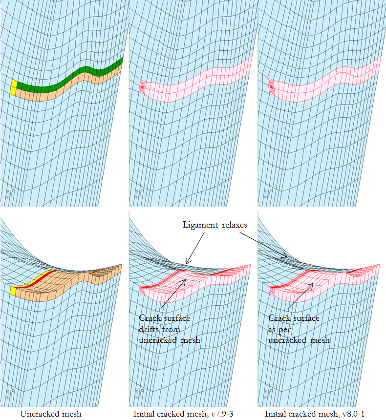
An enhancement is made to the way that initial crack surfaces are created when split sets are defined in a model. Previously if the split sets were such that mesh relaxation smoothed the split element region, the initial crack surface could drift from the position defined in the uncracked mesh. Now the creation of the initial crack surface ensures that the split surface remains in the position defined in the uncracked mesh.
The detailed integration output available via .bk1 or .bk2 files in previous versions of Zencrack has been consolidated to a single .bk file. In addition, if NODE=SELECTED is used when requesting a .bk file, special labels ALL, FIRST and LAST are now allowed on the dataline that specifies the required node positions on the crack front.
In previous releases the default behaviour has been that three contour integrals would be calculated at the crack front even if the crack-blocks being used had more than three rings of elements available. In version 8.0-1 the default behaviour is changed such that all available contours are calculated. The default can also be explicitly requested with a new option ALL on the CONTOURS parameter of *ENERGY RELEASE RATE:
*ENERGY RELEASE RATE, CONTOURS=ALL
The fatigue crack growth scheme in Zencrack integrates in whole cycles by default. To allow integration of part cycles previously required the use of a control tolerance setting:
*CONTROLS, itolpartcyc=1
This control tolerance has been replaced by a new option PART CYCLES=No (or Yes) on keyword *INTEGRATION SCHEME.
Abaqus interface
The use of cylindrical (SYSTEM=C) or spherical (SYSTEM=S) coordinate systems on the *NODE keyword(s) in the uncracked mesh is now supported. Coordinates are immediately converted to the global system.
Zencrack versions prior to 8.0-1 require some manual adjustments in the Zencrack configuration if they are to be used with Abaqus 2016 due to the change in the Abaqus naming convention. These issues are resolved in the 8.0-1 release.
Ansys interface
The use of the "solid model pass" terminology has been changed to "pre-pass". Originally the "solid model pass" was used to run Ansys to process solid model files. The use of an extra initial Ansys run was subsequently expanded for other purposes hence the change to the terminology used to describe such runs.
NX Nastran interface
A check is now made and a warning issued if the JINTEG, CRAKTP or VCEV keywords are found in the uncracked mesh.
Installation
Some improvements are made in the installation program to reduce the amount of user interaction required in the command prompt phase of the process. An option is also added to place a nodelocked license file into the correct location.