
- Software
- Zencrack
- What’s New in Zencrack?
Zencrack 8.1-1
What's New in Zencrack?
Zencrack 8.1-1
Zencrack version 8.1-1 was finalised on 30 January 2017
This release includes:
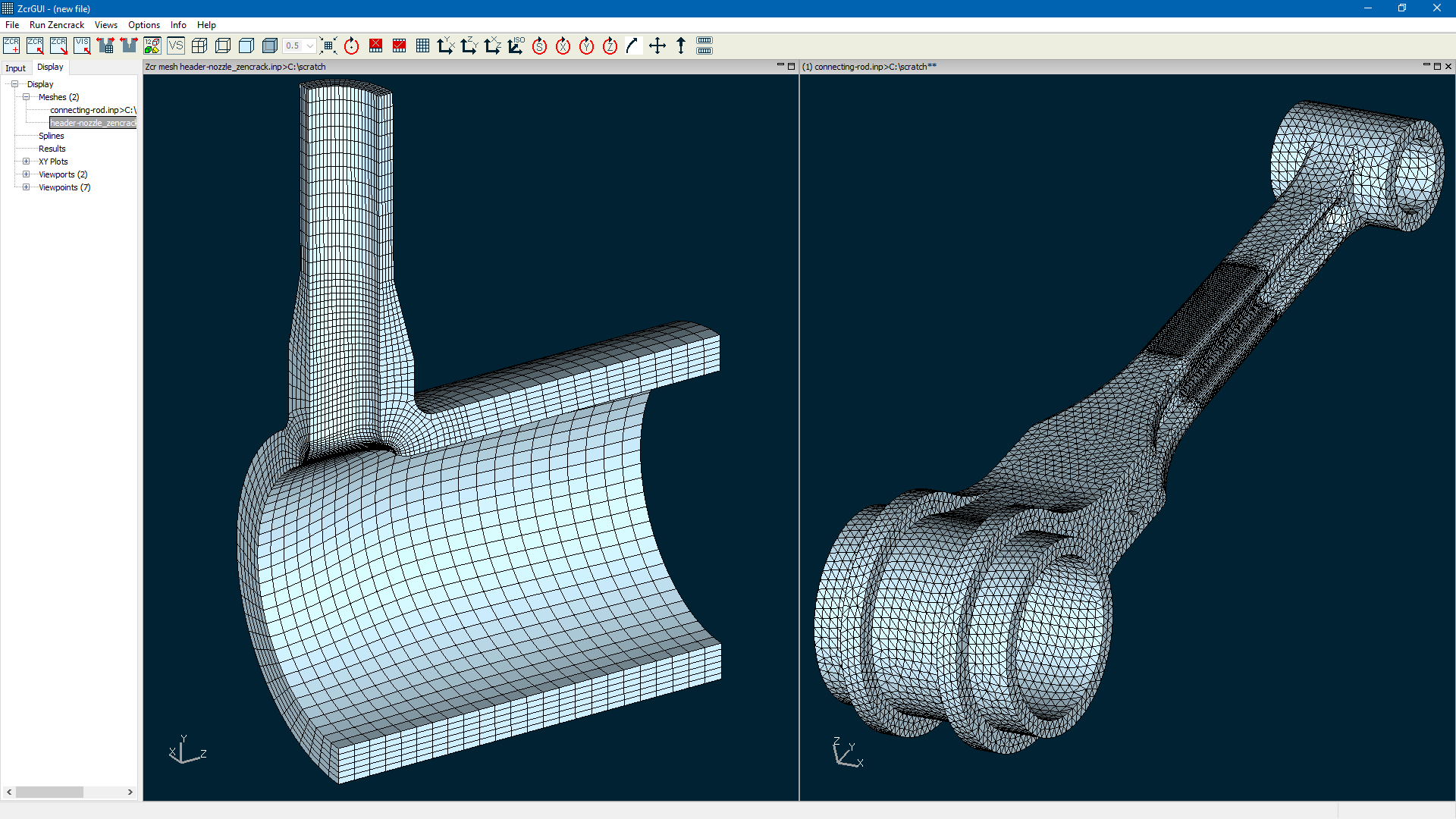
- Improved visualisation performance in the GUI:
- faster and smoother : pan / rotate / zoom
- reduced memory requirement
- new rendering options (e.g. shading, edge options)
- Enhancements in the use of multiple materials.
- Support for Ansys contour integral types: SIFS, TSTRESS, CSTAR.
Zencrack GUI
A number of improvements are made in the rendering of meshes and the interaction of a mesh with display of crack growth profiles:
- Improved visualisation performance
- i.e. faster and smoother : pan / rotate / zoom
- New render options including:
- Addition of shading to filled mode
- Addition of options for edge modes e.g. external / face angle / all egdes etc.
- Optional removal of internal edges and/or faces after making a selection
- Improved clarity for opacity mode
The Views drop-down menu includes additional options related to rendering with four new toolbar icons:
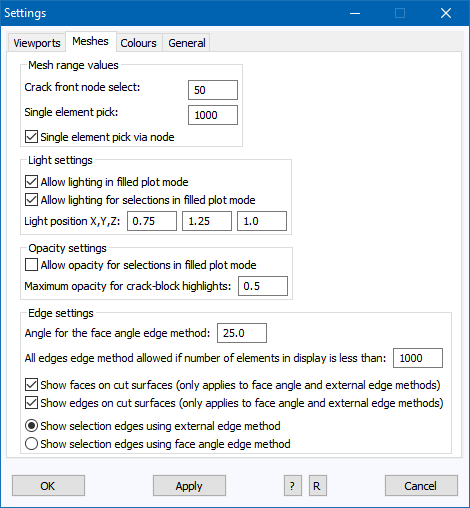
Some options related to control of mesh rendering are available on the expanded Settings screen (Options > Settings). This screen is now split into four tabs.
The Meshes tab contains new rendering option.
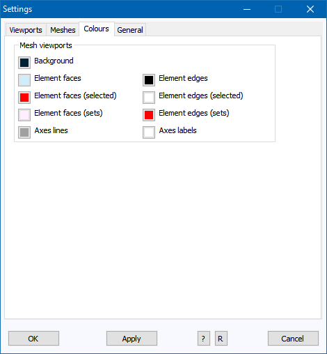
The Colours tab contains an expanded set of colour settings that can be changed without having to restart the GUI. The Viewports tab includes new options to control whether or not xy and mesh plots saved as .png files should have a transparent background.
On the Input Tab in version 8.0-1 the F1 key was used to provide access to information on individual items with warnings and/or errors. In version 8.1-1 the behaviour of the F1 key is changed and functionality is added for the F2 and F3 keys when an item is highlighted in the Input tab:
| F1 | provides access to the hints screen for the item (in most cases the same as accessing the hints from the screen option after opening a screen). |
| F2 | provides a list of warnings and/or errors - this requires that the item is highlight orange, red or blue (i.e. the F1 behaviour in version 8.0-1). |
| F3 | provides confirmation of the keyword data for the item. This requires that the item is bold (i.e. contains non-default data) unless the Options > Settings > General > "Save default values" is set to "Write all values when a .zcr file is saved". |
In addition to allowing direct access to the hints files from the Input tab, the content and layout of the hints information has been improved.
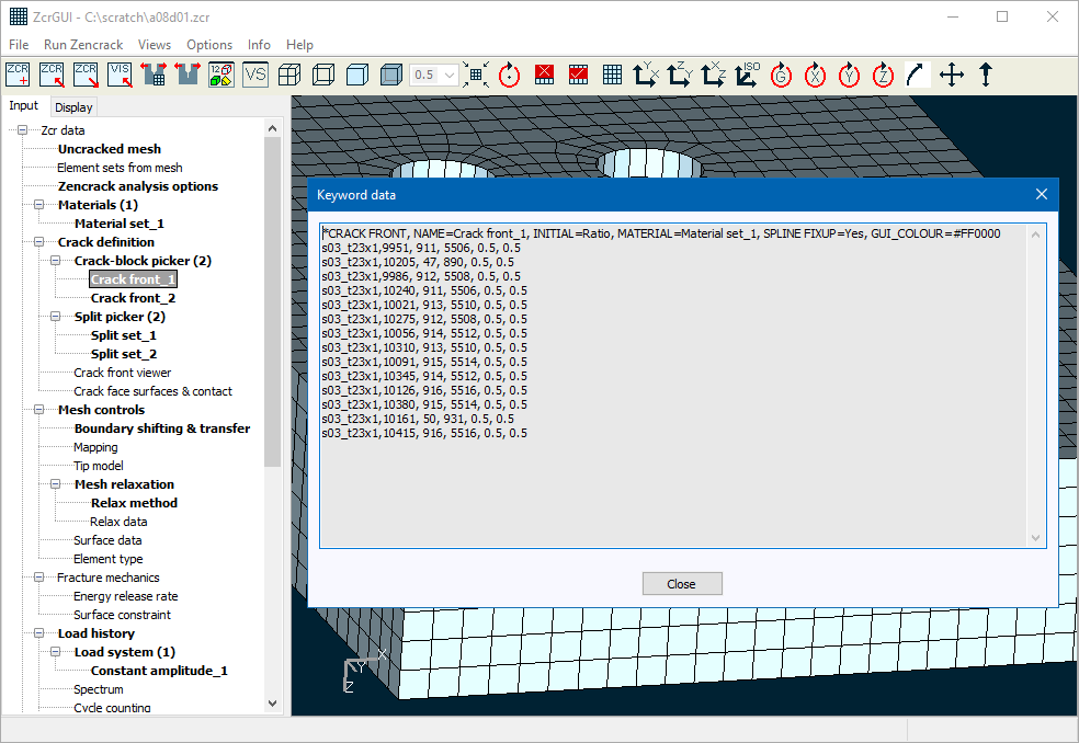
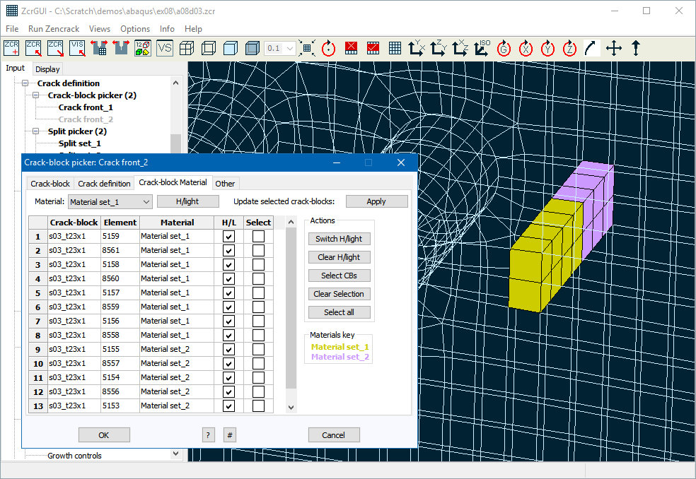
A new tab is added to the crack-block picker screen to support the new capability for multiple materials definition on a crack front. This new tab becomes available when more than one material is defined in the Input tab.
A number of changes are made for results processing:
- More than one results (.vis) file can now be opened at the same time by making a multiple selection in the "Open file" window after selecting "Open results".
- When a results screen is open to access summary information for a set of results (Display tab > Results > double-click a results entry), new options are available:
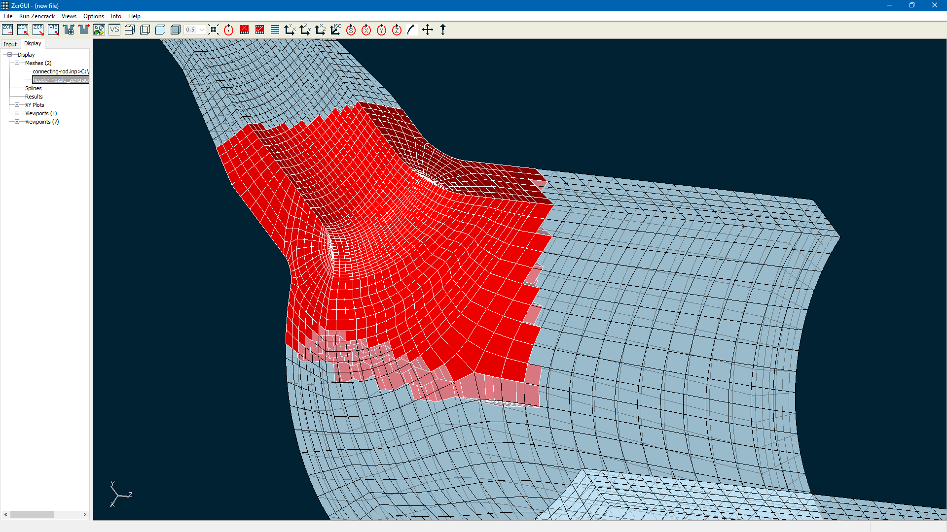
- Right-clicking an entry in the "Crack profiles" section creates a pop-up menu with options "Set all on / Set all off/ Set transfers only". These options control which profiles for the crack front are included for plotting when the display of the crack front is activated. As in version 8.0-1, expanding an individual "Crack profile" entry shows all profiles with italics used to indicate those which are turned off. As before, individual profiles can be toggled on or off with a double-click. The "Set transfers only" option activates only the profiles at the times that crack-block transfer took place (if this option was used in the analysis). The expanded profile list also indicated the profiles at which transfer took place.
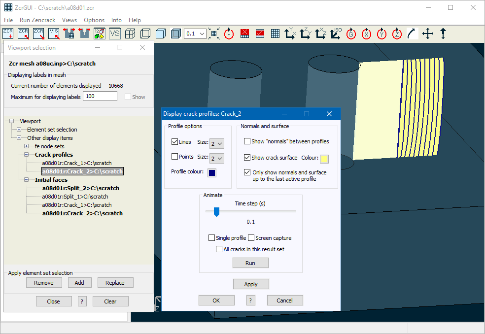
- Crack profile and surface display properties can be accessed as before by double-clicking an entry in the "Crack profiles" or "Initial faces" branch of the Results screen for a results entry. The "Display crack profiles" screen contains new option to control the thickness of the profile lines and to control the display of the surface when some profiles are de-activated.
- Crack profile and surface display properties can now also be accessed directly from the VS screen by right-clicking on an entry in the "Crack profiles" or "Initial faces" branch.
- If a set of crack profiles are active in the viewport when the "Display crack profiles" screen is opened (either via the Results screen or directly from the VS screen), the "Display crack profiles" screen includes a new "Animate" panel. This panel allows the active crack profiles to be animated. Each frame of the animation may optionally be saved to a .png file.
Zencrack changes
The use of multiple materials in a Zencrack input file was introduced in version 8.0-1. In version 8.1-1 that capability is extended to allow material definitions to be associated with each crack front node on a crack front in order to allow analysis of crack front that traverse a material boundary. In the Zencrack input file the material assignment for a crack front via *CRACK FRONT. MATERIAL can be over-ridden for individual crack-blocks by the addition of a material name on the crack-block data line. As the full crack front is constructed, the material definitions for each crack-block are considered in order to associate a material with each crack front node. At the interface node along a crack front between crack-blocks having different material assignments, the program uses the material associated with the lowest numbered crack-block and includes a report of the assignment in the .rep file. For example:
***WARNING
Node position    9 on crack front   1 is connected to crack-blocks with different materials:
Crack-block   7 material id   1 : Material set_1
Crack-block   8 material id   1 : Material set_1
Crack-block   9 material id   2 : Material set_2
Crack-block  10 material id   2 : Material set_2
The node will be process using data for material id   1 : Material set_1.
Care must be taken with the mesh when using this option as the re-meshing process can cause element boundaries to move and may result in the physical movement of a material interface. In some cases it may be sufficient to simply prevent re-distribution of nodes along the crack front by using *CRACK FRONT, SPLINE FIXUP=No (e.g. supplied example 03 in folder ex08). In other cases, user subroutine user_material_id can be used to assign a material id based on current crack front coordinates. It may also be necessary to adopt such an approach for the f.e. model (e.g. Abaqus user subroutine usdfld to define material properties via a state variable).
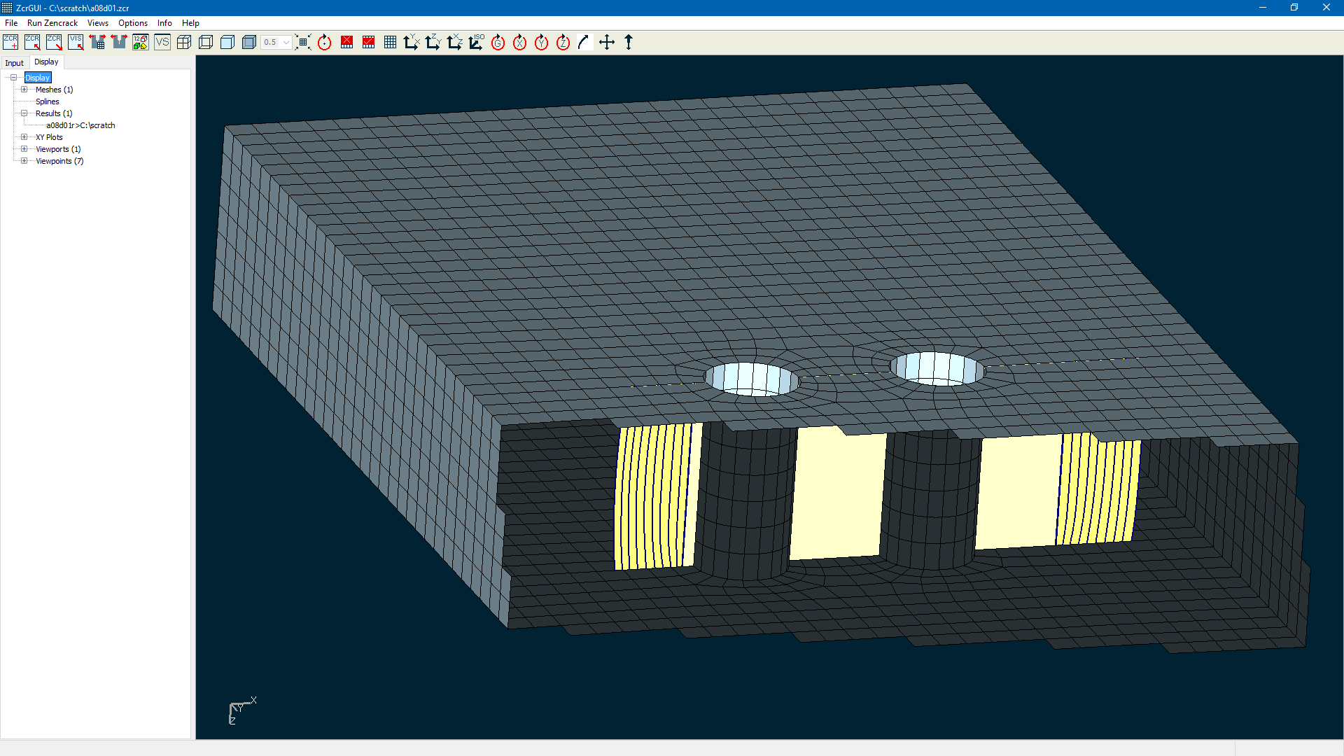
Load and surface updates on the crack face when only one side of the crack is modelled now extend automatically to new rows of elements if the model contains standard through crack-blocks which transfer across rows as the crack grows. In previous releases it was necessary to include any such load on the ligament so that the new region of crack face was correctly loaded as the crack-blocks transferred to the next row. The supplied example ex10 includes a model with this type of crack and crack face loading.
Surface definitions on the initial crack faces when both sides of the crack are modelled now extend automatically to new rows of elements if the model contains standard through crack-blocks which transfer across rows as the crack grows.
Several new tolerances are added to the *TOLERANCE keyword. Most of the time these can be left at their default values. Two new items that have been added may result in small differences in analysis results compared to previous Zencrack releases when the error control scheme is used to control the step size between f.e. analyses. In previous releases the "maximum error" term was calculated for every corner node on the crack front in order to identify the value to be used to control the step. In some cases the overall maximum could be identified on a node with small K or small growth. For example:
- At nodes close to a changeover region along a crack front from a growth zone to a no-growth zone.
- At a node on a crack front that is growing much more slowly than nodes on other crack fronts in a model when multiple cracks are being analysed.
In such cases the step size could be made smaller than necessary. The new tolerances allow nodes to be ignored when evaluating the error term for step control if they satisfy conditions that the ratio of their G or da values to the largest values in the model are less than a specified limit. If such conditions are met, the note below is reported in the .rep file and the tables containing the error values include an a and/or g to indicate the affected nodes.
LARGEST ERROR IN G FOR THIS RESULTS SET IS      -0.115691%
NOTE [a]: Nodes with da/maximumDA<0.10000 have not been used when defining the largest error
NOTE [g]: Nodes with abs(sqrt(|G|)/sqrt(|maximumG|))<0.10000 have not been used when defining the largest error
This behaviour can be de-activated (i.e. to revert to 8.0-1 behaviour) by using appropriate input values - refer to the *TOLERANCE keyword in the Input Formats Manual.
An option is also included to allow the nodes at the ends of crack front to be excluded when calculating the error term.
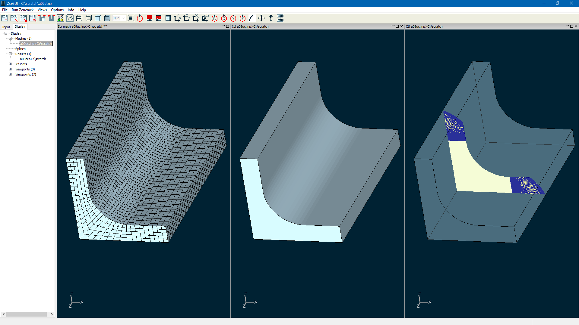
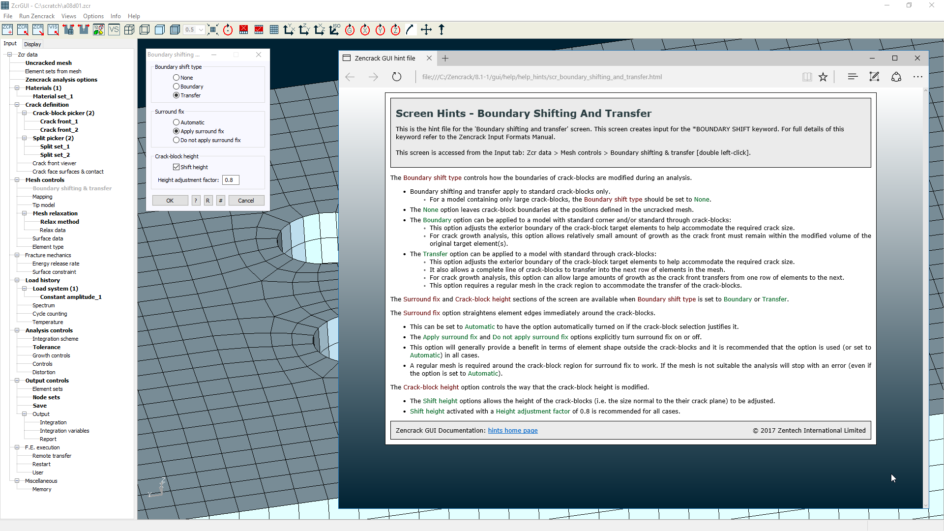
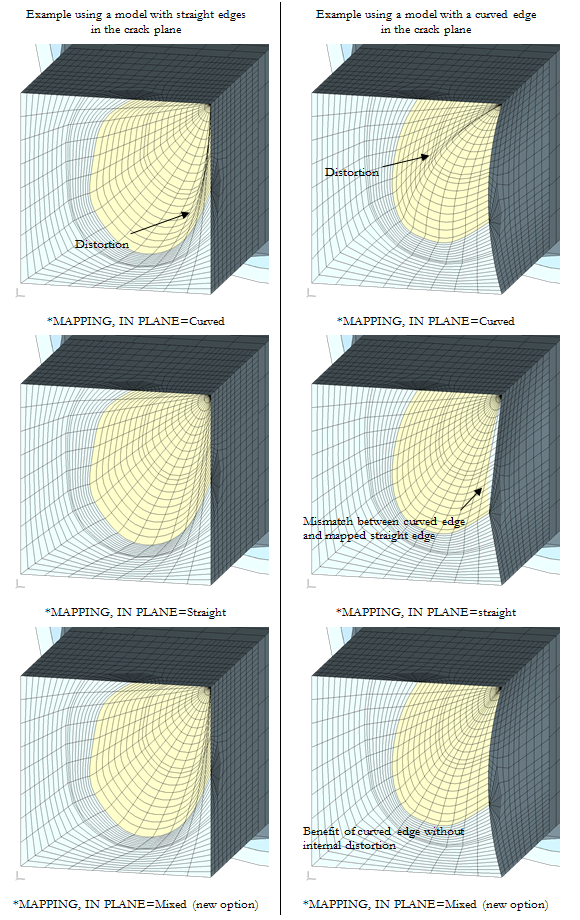
A new value INPLANE=Mixed on the *MAPPING keyword allows transition from a curved fixup at the edge of crack-blocks to a straight fixup up half way along the crack front of the crack-block. When the default INPLANE=Curved option is used for very distorted crack fronts (i.e. high value of the edge 1 to edge 2 ratio), there can be distortion within the crack plane. So the alternative INPLANE=Straight option is beneficial. But the end node may require a curved fixup to maintain curved outer surfaces of the block. So a transition function is defined from curved to straight. The new *MAPPING, MIXED FACTOR=value option can be used to control the transition. A value of 0 gives curved behaviour. Values greater than 0 control the transition to straight fixup (i.e. the higher the value, the faster the transition to a straight fixup). Examples of the differences between the curved, straight and mixed options are shown for two crack front shapes in two crack plane geometries, below.
There are stability improvements in some aspects of the crack-block mapping process. Also in the creation of the initial crack front when *CRACK FRONT, INITIAL=Points is used. If the mapping fails for some reason, some areas of the code now allow the process to continue to generate a failed mesh to help understand any underlying issues contributing to the failure.
A number of updates are made in relation to the rainflow counting program supplied with Zencrack (see below). In addition, if a rainflow count is required during a Zencrack analysis, the version details of the rainflow program are now included in the .rep file (during the processing of the *CYCLE COUNT keyword).
Abaqus interface
The Abaqus *FILM keyword is now processed for film coefficient updates in the crack region. Previously film coefficient updates were only supported if applied via *SFILM and appropriate surface definitions.
Processing of body force types BX, BY and BZ is supported in the crack region.
All load types that can be updated are now updated across all analysis steps. Previously updates were only possible in one load step.
The Abaqus *DISTRIBUTION, LOCATION=ELEMENT option is now processed and updated for crack-block elements. When the update is carried out the distribution values applied to the target elements are applied to all elements of the crack-block that replace the target element.
Ansys interface
Support is added for calculation of three additional contour integral types available in Ansys:
- SIFS
- TSTRESS
- CSTAR
The SIFS and TSTRESS requests are made via parameters K FACTORS and T-STRESS on the *ENERGY RELEASE RATE keyword. They are allowed when the main requested contour integral is the J-integral (i.e. *ENERGY RELEASE RATE , TYPE=J). The request for SIFS produces values for K1, K2 and K3 and interaction integrals IIN1, IIN2 and IIN3.
The C*-integral described in the Ansys documentation can be requested in a creep analysis by using *ENERGY RELEASE RATE, TYPE=Ct.
Results of all of these contour integral options can be used for XY plotting in the Zencrack GUI.
The Ansys SFE load type CONV is now processed for film coefficient updates in the crack region. Non-uniform values can be updated with the use of the Zencrack subroutine user_ansys_cbload.
All load types that can be updated are now updated across all analysis steps. Previously updates were only possible in one load step.
Transition elements for large crack-blocks are allowed if the surfaces are defined using surface element (i.e. EN) of type 170, 173 or 174. Previously only ESURF definitions were processed in relation to creation of transition elements.
User subroutines
The new subroutine user_material_id allows a material id to be assigned to a crack front node before results of the f.e. analysis are processed. The subroutine is intended for cases where multiple materials are defined in a model and the crack front may cross the material boundary during the analysis.
The subroutine user_ansys_cbload replaces the previous user_cbpressure subroutine. This subroutine allows update of non-uniform SFE pressure load in the crack regions and is updated to also handle non-uniform film coefficients.
Utility program RAINFLOW
The RAINFLOW program is upgraded with some changes in the way that residuals are handled towards the end of the counting process. These changes may produce small differences in the counted spectrum sequence compared to previous versions. The command line option "-residual 2" can be used to force the residual method used in previous versions.
The command line for the RAINFLOW program is changed to allow pairs of "option value" in a similar fashion to the command line used to run Zencrack jobs. For example:
rainflow -j input.dat -reportfile rain.rep
Several new options are introduced for the command line including an option to ignore counted cycles if their range is below a specified value.
Utility program PROCESS
A new "maximum" method of data extraction is added. For each f.e. step this method considers all nodes on a crack front and extracts results for the node with the maximum of a selected variable. Currently two such variables are supported:
- Ki calculated from displacements
- Ki calculated by mode I conversion from Gmax.
This option is available when the PROCESS program is executed from the command line but is not currently supported when PROCESS is used by the GUI to extract XY data.
Support is added for extraction and processing of additional contour integral variables:
- Abaqus K FACTORS contour integrals.
- Ansys SIFS, TSTRESS and CSTAR contour integrals.
The additional Abaqus results variables provided by this are: K1, K2, K3, JKS, CPD.
The additional Ansys results variables provided by this are: K1, K2, K3, IIN1, IIN2, IIN3, TSTRESS, CSTAR.
When the PROCESS program is used by the GUI to extract data for plotting these variables are available in the list of plot variables on the GUI plotting screens (if they were calculated in an analysis).
The creep contour integral is described as the Ct-integral in Abaqus documentation and the C*-integral in Ansys documentation. For Zencrack input definition, for input and XY plotting in the GUI and within the .csv file generated by the PROCESS program, both are described as the Ct-integral.
A change is made to some of the headers in the .csv file when Ct-integrals are being reported to clarify that some columns contain Ct-integral data not J-integral data and that some columns are not applicable (but may contain zeros).