
- Software
- Zencrack
- Zencrack GUI
Pre-processing
Zencrack GUI
Pre-processing
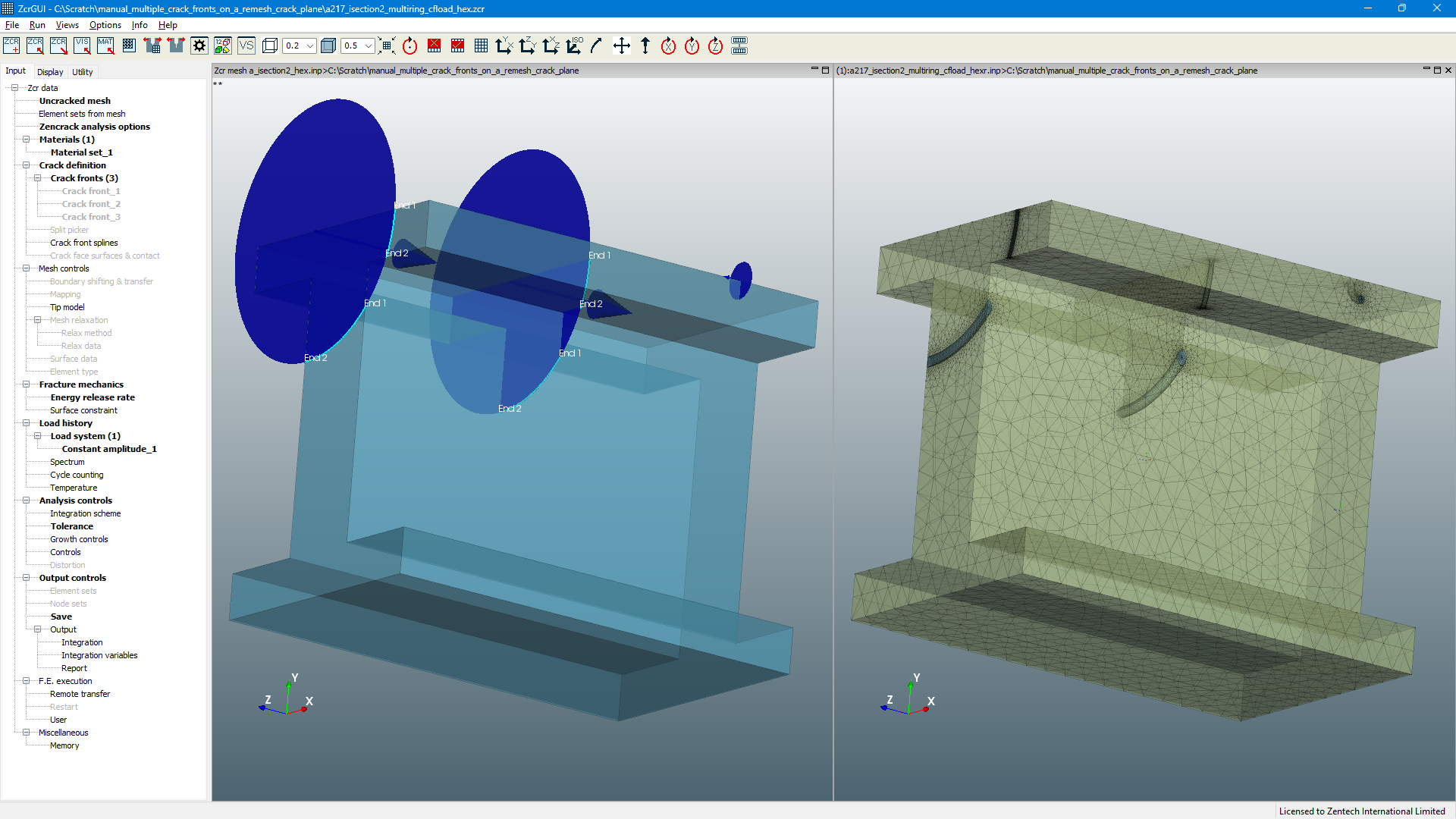
The Zencrack GUI contains a left side pane with 'Input', 'Display' and 'Utility' tabs. The Input tab contains the options for defining Zencrack input data.
The branches of the Input tab tree hold the input file contents. Mesh related items are defined by data picked from an imported uncracked mesh. An existing input file can be opened to populate the tree to allow review and modification of the data.
The following sections describe some features in the Input tree of the GUI.
Uncracked Mesh
The "uncracked mesh" branch, allows specification of the uncracked mesh by selection of a file from a folder. The mesh is then imported via the import mesh button. The origin of the uncracked mesh file is not important - it may have been generated in Abaqus/CAE, Ansys/APDL, Ansys/Workbench, NX or any other pre-processor.
Mesh import has the following features:
- Display of first and second order tet, prism and brick elements.
- Import of element sets (Abaqus) or element components (Ansys) from the uncracked mesh for display in the GUI.
- Option to import or ignore data from "included" input files (i.e. data defined via Abaqus *INCLUDE, Ansys /INPUT or Simcenter Nastran INCLUDE options).
Element Sets
Two types of element set are handled in the GUI - sets imported from the f.e. input file, and sets created in the element sets tree entry. Sets created in the GUI are edited by adding or removing elements selected in the current view. Such sets are saved in the Zencrack input file and can optionally be exported to the cracked mesh files.
Materials
One or more materials may be defined for an analysis. Each crack front is cross-referenced to a material definition. The material data may include:
- Basic data (e.g. Young's modulus, poisson ratio).
- Fatigue and/or time dependent crack growth law.
- Threshold definition.
- Retardation data if an empiricdal retardation law is being used in the analysis.
Material data, once defined, may be exported to a folder for later import into another input file. This allows re-use of materials data without the need to re-enter the full set of data.
Crack Definition (Remeshing Method)
Crack definition is carried out using the "Crack fronts" branch of the tree:
- The crack definition is split into crack type, geometric data, ring definition and remesh region definition.
- Separate previews are possible of each aspect of the crack definition.
- Full preview of the remeshing for the crack definition allows the initial cracked mesh to be checked.
Crack Definition (Crack-block Method)
Crack definition is carried out using four sub-entries on the "Crack fronts" branch of the tree:
- The "crack-block picker" allows definition of one or more crack fronts. Element and node data required to define the crack fronts is picked directly from the model.
- For some crack geometries it may be necessary to separate elements to form extended parts of the initial crack faces. This can be done by picking element data with the "split element picker".
- The "crack front viewer" allows definition and visualisation of an initial crack front as a series of points in space.
- Crack face surfaces and/or contact definitions can be created if required.
Mesh Controls
The "mesh controls" group defines the crack front tip model.
For the crack-block method the "mesh controls" group also defines data for the boundary shift, relaxation and surface definition options. These options control aspects of the remeshing process as the crack grows through the component.
Load History
The "load history" group allows definition of the load sequence to be used for crack growth integration. This may range from constant amplitude loading to complex thermo-mecanical load cycles. The load history definition includes cross-referencing to the load steps and increments definied in the finite element model.
Analysis Controls
The "analysis controls" group allows definition of tolerances and parameters which control aspects of the re-meshing and crack growth solution.
Output Controls
The "output controls" group allows creation of crack-related element and node sets in the cracked mesh. It also allows f.e. output files from one or more steps of a crack growth analysis to be saved (e.g. the .odb, .db or .op2 files). Detailed integration output for one or more crack front nodes can also be requested in this section.
F.E. Execution
The "f.e. execution" group allows control of some aspects related to the finite element analyses carried out as part of the analysis.
Miscellaneous
The "miscellaneous" group allows manual definition of some memory-related parameters.
Zencrack
Zencrack GUI
More in this category